Achieve general-purpose I/O expansion with MCP23S17 and PIC18F4585
Plug, Play, Expand: Redefining connectivity with port expanders!

Published Nov 01, 2023
Click board™
EXPAND Click
Dev. board
EasyPIC v8
Compiler
NECTO Studio
MCU
PIC18F4585
Expand your project's input and output capabilities without complex wiring or hardware modifications
A
A
Hardware Overview
How does it work?
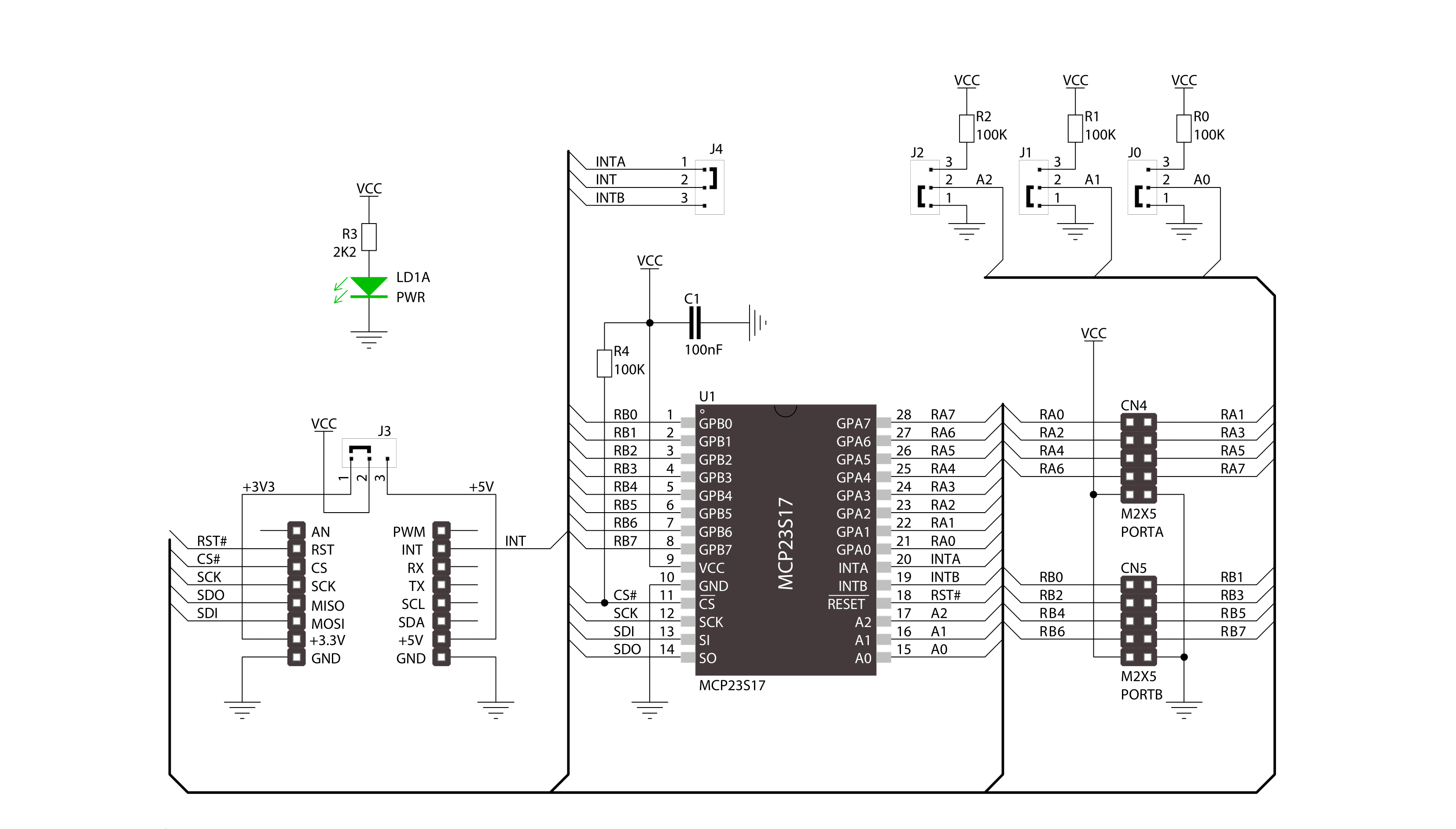
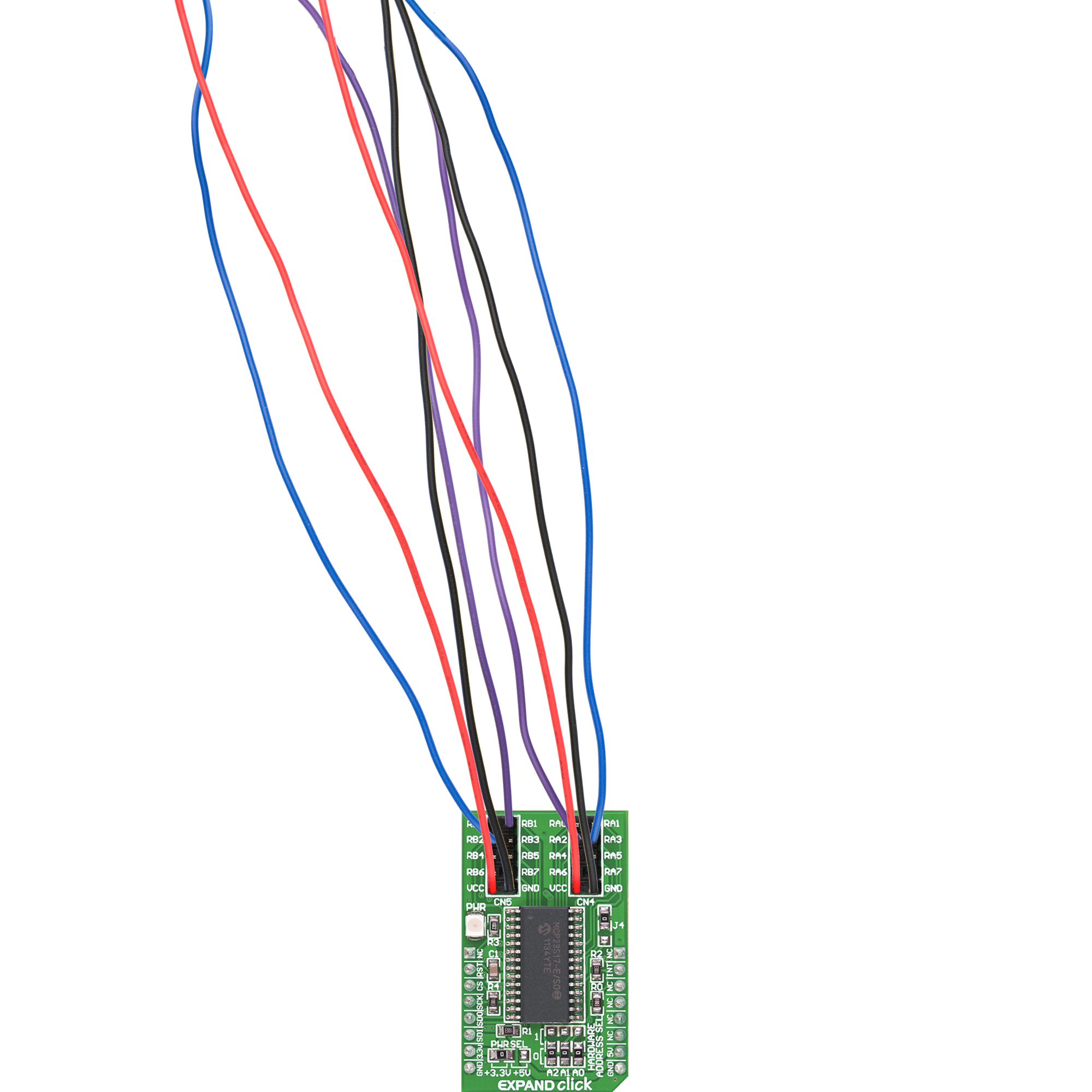
Expand Click is based on the MCP23S17, a 16-bit general-purpose parallel I/O expansion with the serial interface from Microchip. The MCP23S17 consists of multiple 8-bit configuration registers for input, output, and polarity selection. The host MCU can enable the I/Os as either inputs or outputs by writing the I/O configuration bits with data for each input or output kept in the corresponding input or output register. This port expander represents a simple solution when additional I/Os are needed while keeping interconnections to a minimum. It features two double-row unpopulated headers for connecting I/O devices. This Click board™ communicates with MCU using the standard 4-Wire
SPI serial interface with a maximum 10MHz frequency. The MCP23S17 has a 7-bit slave address with the first four MSBs fixed to 0100. The address pins A0, A1, and A2 are programmed by the user and determine the value of the last three LSBs of the slave address, which can be selected by positioning onboard SMD jumpers labeled as HARDWARE ADDRESS SEL to an appropriate position marked as 1 or 0. This way, the MCP23S17 provides the opportunity to use more Extend Clicks on a single host MCU. Besides, it also has an interrupt feature, routed to the INT pin of the mikroBUS™ socket, indicating to the host controller that an input state has been changed
alongside the general reset feature. Two interrupt pins on the MCP23S17 can be associated with their respective ports or logically OR’ed together so that both pins will activate if either port causes an interrupt. The desired interrupt port can be selected by positioning an onboard SMD jumper labeled J4 in an appropriate position. This Click board™ can operate with either 3.3V or 5V logic voltage levels selected via the PWR SEL jumper. This way, both 3.3V and 5V capable MCUs can use the communication lines properly. Also, this Click board™ comes equipped with a library containing easy-to-use functions and an example code that can be used for further development.

Features overview
Development board
EasyPIC v8 is a development board specially designed for the needs of rapid development of embedded applications. It supports many high pin count 8-bit PIC microcontrollers from Microchip, regardless of their number of pins, and a broad set of unique functions, such as the first-ever embedded debugger/programmer. The development board is well organized and designed so that the end-user has all the necessary elements, such as switches, buttons, indicators, connectors, and others, in one place. Thanks to innovative manufacturing technology, EasyPIC v8 provides a fluid and immersive working experience, allowing access anywhere and under any
circumstances at any time. Each part of the EasyPIC v8 development board contains the components necessary for the most efficient operation of the same board. In addition to the advanced integrated CODEGRIP programmer/debugger module, which offers many valuable programming/debugging options and seamless integration with the Mikroe software environment, the board also includes a clean and regulated power supply module for the development board. It can use a wide range of external power sources, including a battery, an external 12V power supply, and a power source via the USB Type-C (USB-C) connector.
Communication options such as USB-UART, USB DEVICE, and CAN are also included, including the well-established mikroBUS™ standard, two display options (graphical and character-based LCD), and several different DIP sockets. These sockets cover a wide range of 8-bit PIC MCUs, from the smallest PIC MCU devices with only eight up to forty pins. EasyPIC v8 is an integral part of the Mikroe ecosystem for rapid development. Natively supported by Mikroe software tools, it covers many aspects of prototyping and development thanks to a considerable number of different Click boards™ (over a thousand boards), the number of which is growing every day.

Microcontroller Overview
MCU Card / MCU
Architecture
PIC
MCU Memory (KB)
48
Silicon Vendor
Microchip
Pin count
40
RAM (Bytes)
3328
Used MCU Pins
mikroBUS™ mapper
Take a closer look
Click board™ Schematic
Step by step
Project assembly

Start by selecting your development board and Click board™. Begin with the EasyPIC v8 as your development board.


Software Support
Library Description
This library contains API for EXPAND Click driver.
Key functions:
expand_set_direction_port_a- Set expander PORTA direction functionexpand_write_port_a- Write one byte of data to register for PORTA functionexpand_reset- Reset function
Open Source
Code example
The complete application code and a ready-to-use project are available through the NECTO Studio Package Manager for direct installation in the NECTO Studio. The application code can also be found on the MIKROE GitHub account.
/*!
 * \file
 * \brief Expand Click example
 *
 * # Description
 * This applicatioin use for expansion I/O lines.
 *
 * The demo application is composed of two sections :
 *
 * ## Application Init
 * Initialization driver enable's - GPIO,
 * reset MCP23S17 chip, set PORTA to be output and PORTB to be input,
 * set default configuration and start write log.
 *
 * ## Application Task
 * This is a example which demonstrates the use of Expand Click board.
 * Expand Click communicates with register via SPI protocol by write and read from register,
 * set configuration and state and read configuration and state.
 * Results are being sent to the Usart Terminal where you can track their changes.
 * All data logs on usb uart for aproximetly every 500 ms.
 *
 * \author MikroE Team
 *
 */
// ------------------------------------------------------------------- INCLUDES

#include "board.h"
#include "log.h"
#include "expand.h"

// ------------------------------------------------------------------ VARIABLES

static expand_t expand;
static log_t logger;

static uint8_t port_status;
static uint8_t position;
static uint16_t pin_position;

void application_init ( void )
{
    log_cfg_t log_cfg;
    expand_cfg_t cfg;

    /**
     * Logger initialization.
     * Default baud rate: 115200
     * Default log level: LOG_LEVEL_DEBUG
     * @note If USB_UART_RX and USB_UART_TX
     * are defined as HAL_PIN_NC, you will
     * need to define them manually for log to work.
     * See @b LOG_MAP_USB_UART macro definition for detailed explanation.
     */
    LOG_MAP_USB_UART( log_cfg );
    log_init( &logger, &log_cfg );
    log_info( &logger, "---- Application Init ----" );

    //  Click initialization.

    expand_cfg_setup( &cfg );
    EXPAND_MAP_MIKROBUS( cfg, MIKROBUS_1 );
    expand_init( &expand, &cfg );

    expand_default_configuration( &expand, EXPAND_SPI_MODULE_POSITION_0 );

    expand_set_direction_port_a( &expand, EXPAND_SPI_MODULE_POSITION_0, EXPAND_PORT_DIRECTION_OUTPUT );

    expand_set_direction_port_b( &expand, EXPAND_SPI_MODULE_POSITION_0, EXPAND_PORT_DIRECTION_INPUT );

    expand_set_pull_ups_port_b( &expand, EXPAND_SPI_MODULE_POSITION_0, 0xFF );
}

void application_task ( void )
{
    pin_position = 1;

    for ( position = 0; position < 8; position++ )
    {
        expand_write_port_a( &expand, EXPAND_SPI_MODULE_POSITION_0, pin_position );
        log_printf( &logger, " PA%d set\r\n", (uint16_t) position );

        port_status = expand_read_port_b( &expand, EXPAND_SPI_MODULE_POSITION_0 );

        log_printf( &logger, " Status PB (input) : %d  \r\n", (uint16_t) port_status );
        log_printf( &logger, "----------------\r\n" );

        pin_position <<= 1;

        Delay_ms ( 500 );
    }
}

int main ( void )
{
    /* Do not remove this line or clock might not be set correctly. */
    #ifdef PREINIT_SUPPORTED
    preinit();
    #endif

    application_init( );

    for ( ; ; )
    {
        application_task( );
    }

    return 0;
}


// ------------------------------------------------------------------------ END


