Accelerate your CAN applications with ATA6571 and PIC18LF46K40
The road to efficiency starts with our HS CAN
Published Aug 03, 2023
Click board™
ATA6571 Click
Dev. board
EasyPIC v8
Compiler
NECTO Studio
MCU
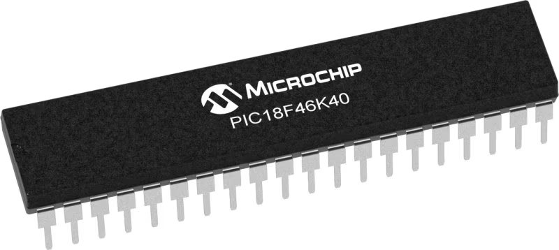
PIC18LF46K40
Experience the future of high-speed communication with our cutting-edge CAN FD transceiver solution
A
A
Hardware Overview
How does it work?
ATA6571 Click is based on the ATA6571, a standalone high-speed CAN FD transceiver up to 5 Mbit/s that interfaces a Controller Area Network (CAN) protocol controller and the physical two-wire CAN bus from Microchip. It offers improved Electromagnetic Compatibility (EMC) and ESD performance. Its advanced low-power management with local and remote Wake-Up support makes achieving low current consumption in Standby and Sleep mode possible, even when the internal I/O and transceiver supplies are switched off. The ATA6571 supports functional safety-related applications. Internal Safety Mechanisms prevent device malfunction due to undervoltage and overtemperature, detect bus dominant and recessive clamping, and prevent blocking of the CAN bus due to permanent dominant or recessive states of RXD and TXD. The ATA6571 has one pin for waking the device from Sleep mode. This pin is connected to a WAKE external switch to generate a local Wake-Up function. A Wake-Up event on the
CAN bus switches the inhibit output pin INH to the High level. The INH pin provides an internal switch towards the battery supply voltage and controls external voltage regulators, the MCP1804 from Microchip. Through SMD jumpers labeled as JMP3V3 and JMP5V, the LDO's output voltages can power up the mikroBUS™ 3.3V and 5V power rails. However, it should be noted that MIKROE does not advise powering up their systems this way. That is why these jumpers are left unpopulated by default. The ATA6571 communicates with MCU using the UART interface with the default baud rate of 9600 bps for data transfer. In addition to UART communication pins from the mikroBUS™ socket, the user can connect the TX/RX signals directly through the UART External header on the board's left edge. This Click board™ comes equipped with the standard DB-9 connector, making interfacing with the CAN bus simple and easy. Besides, the user can connect the CAN signals directly through the CAN External header, also on the board's left
edge. In addition to these features, the ATA6571 uses several GPIO pins connected to the mikroBUS™ socket. The EN pin routed on the CS pin of the mikroBUS™ is used for Enable Control. Together with the STB pin routed on the AN pin of the mikroBUS™ socket, which represents Standby Mode Control, the EN pin controls the device's operating mode. It also provides a pull-down to force the transceiver into Recessive mode if EN is disconnected. Next to these pins, the ATA6571 uses another pin labeled ERR routed on the RST pin of the mikroBUS™ used as Error Indication. This pin reflects the device status and can be visually displayed using the LED indicator labeled as ERR. This Click board™ is designed to operate with both 3.3V and 5V logic voltage levels selected via the VIO SEL jumper. It allows both 3.3V and 5V capable MCUs to use the UART communication lines properly. Also, this Click board™ comes equipped with a library containing easy-to-use functions and an example code that can be used, as a reference, for further development.

Features overview
Development board
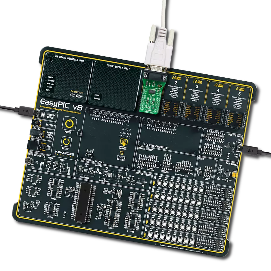
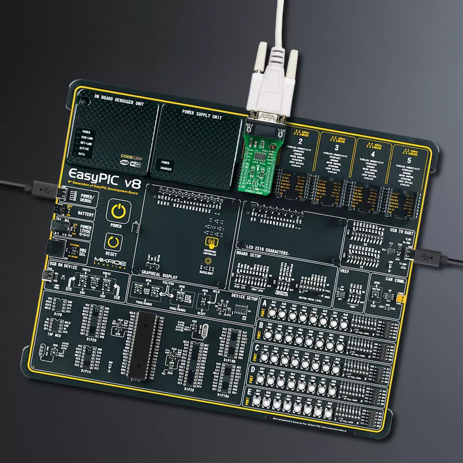
EasyPIC v8 is a development board specially designed for the needs of rapid development of embedded applications. It supports many high pin count 8-bit PIC microcontrollers from Microchip, regardless of their number of pins, and a broad set of unique functions, such as the first-ever embedded debugger/programmer. The development board is well organized and designed so that the end-user has all the necessary elements, such as switches, buttons, indicators, connectors, and others, in one place. Thanks to innovative manufacturing technology, EasyPIC v8 provides a fluid and immersive working experience, allowing access anywhere and under any
circumstances at any time. Each part of the EasyPIC v8 development board contains the components necessary for the most efficient operation of the same board. In addition to the advanced integrated CODEGRIP programmer/debugger module, which offers many valuable programming/debugging options and seamless integration with the Mikroe software environment, the board also includes a clean and regulated power supply module for the development board. It can use a wide range of external power sources, including a battery, an external 12V power supply, and a power source via the USB Type-C (USB-C) connector.
Communication options such as USB-UART, USB DEVICE, and CAN are also included, including the well-established mikroBUS™ standard, two display options (graphical and character-based LCD), and several different DIP sockets. These sockets cover a wide range of 8-bit PIC MCUs, from the smallest PIC MCU devices with only eight up to forty pins. EasyPIC v8 is an integral part of the Mikroe ecosystem for rapid development. Natively supported by Mikroe software tools, it covers many aspects of prototyping and development thanks to a considerable number of different Click boards™ (over a thousand boards), the number of which is growing every day.

Microcontroller Overview
MCU Card / MCU
Architecture
PIC
MCU Memory (KB)
64
Silicon Vendor
Microchip
Pin count
40
RAM (Bytes)
3728
You complete me!
Accessories
DB9 Cable Female-to-Female (2m) cable is essential for establishing dependable serial data connections between devices. With its DB9 female connectors on both ends, this cable enables a seamless link between various equipment, such as computers, routers, switches, and other serial devices. Measuring 2 meters in length, it offers flexibility in arranging your setup without compromising data transmission quality. Crafted with precision, this cable ensures consistent and reliable data exchange, making it suitable for industrial applications, office environments, and home setups. Whether configuring networking equipment, accessing console ports, or utilizing serial peripherals, this cable's durable construction and robust connectors guarantee a stable connection. Simplify your data communication needs with the 2m DB9 female-to-female cable, an efficient solution designed to meet your serial connectivity requirements easily and efficiently.

Used MCU Pins
mikroBUS™ mapper
Take a closer look
Click board™ Schematic

Step by step
Project assembly

Start by selecting your development board and Click board™. Begin with the EasyPIC v8 as your development board.


Software Support
Library Description
This library contains API for ATA6571 Click driver.
Key functions:
ata6571_set_operating_mode- This function sets the device operating mode by controlling the EN and NSTB pinsata6571_generic_write- This function writes a desired number of data bytes by using UART serial interfaceata6571_generic_read- This function reads a desired number of data bytes by using UART serial interface
Open Source
Code example
The complete application code and a ready-to-use project are available through the NECTO Studio Package Manager for direct installation in the NECTO Studio. The application code can also be found on the MIKROE GitHub account.
/*!
 * @file main.c
 * @brief ATA6571 Click Example.
 *
 * # Description
 * This example reads and processes data from ATA6571 Clicks.
 *
 * The demo application is composed of two sections :
 *
 * ## Application Init
 * Initializes the driver and sets the device operating mode.
 *
 * ## Application Task
 * Depending on the selected demo application mode, it reads all the received data or
 * sends the desired message every 2 seconds.
 *
 * ## Additional Function
 * - static void ata6571_clear_app_buf ( void )
 * - static err_t ata6571_process ( void )
 *
 * @author Stefan Filipovic
 *
 */

#include "board.h"
#include "log.h"
#include "ata6571.h"

#define PROCESS_BUFFER_SIZE 200

/*** Demo application mode selection, only one mode should be selected at the same time ***/
#define DEMO_APP_RECEIVER
// #define DEMO_APP_TRANSMITTER

#define TEXT_TO_SEND           "MikroE - ATA6571 Click board\r\n"

static ata6571_t ata6571;
static log_t logger;

static char app_buf[ PROCESS_BUFFER_SIZE ] = { 0 };
static int32_t app_buf_len = 0;
static int32_t app_buf_cnt = 0;

/**
 * @brief ATA6571 clearing application buffer.
 * @details This function clears memory of application buffer and reset it's length and counter.
 * @note None.
 */
static void ata6571_clear_app_buf ( void );

/**
 * @brief ATA6571 data reading function.
 * @details This function reads data from device and concatenates data to application buffer.
 *
 * @return @li @c  0 - Read some data.
 *         @li @c -1 - Nothing is read.
 *         @li @c -2 - Application buffer overflow.
 *
 * See #err_t definition for detailed explanation.
 * @note None.
 */
static err_t ata6571_process ( void );

void application_init ( void )
{
    log_cfg_t log_cfg;          /**< Logger config object. */
    ata6571_cfg_t ata6571_cfg;  /**< Click config object. */

    /**
     * Logger initialization.
     * Default baud rate: 115200
     * Default log level: LOG_LEVEL_DEBUG
     * @note If USB_UART_RX and USB_UART_TX
     * are defined as HAL_PIN_NC, you will
     * need to define them manually for log to work.
     * See @b LOG_MAP_USB_UART macro definition for detailed explanation.
     */
    LOG_MAP_USB_UART( log_cfg );
    log_init( &logger, &log_cfg );
    Delay_ms ( 100 );
    log_info( &logger, " Application Init " );

    // Click initialization.

    ata6571_cfg_setup( &ata6571_cfg );
    ATA6571_MAP_MIKROBUS( ata6571_cfg, MIKROBUS_1 );
    err_t init_flag = ata6571_init( &ata6571, &ata6571_cfg );
    if ( UART_ERROR == init_flag )
    {
        log_error( &logger, " Application Init Error. " );
        log_info( &logger, " Please, run program again... " );

        for ( ; ; );
    }
    Delay_ms ( 100 );

#ifdef DEMO_APP_RECEIVER
    log_printf( &logger, "---- RECEIVER MODE ----\r\n" );
#endif
#ifdef DEMO_APP_TRANSMITTER
    log_printf( &logger, "---- TRANSMITTER MODE ----\r\n" );
#endif

    ata6571_set_operating_mode ( &ata6571, ATA6571_OPERATING_MODE_NORMAL );
    app_buf_len = 0;
    app_buf_cnt = 0;

    log_info( &logger, " Application Task " );
    Delay_ms ( 100 );
}

void application_task ( void )
{
#ifdef DEMO_APP_RECEIVER
    ata6571_process();

    if ( app_buf_len > 0 )
    {
        Delay_ms ( 100 );
        ata6571_process();

        log_printf( &logger, "%s", app_buf );
        log_printf( &logger, "-------------------------------------\r\n" );
        ata6571_clear_app_buf(  );
    }
#endif

#ifdef DEMO_APP_TRANSMITTER
    ata6571_generic_write( &ata6571, TEXT_TO_SEND, strlen( TEXT_TO_SEND ) );
    log_printf( &logger, "---- The message has been sent ----\r\n" );
    Delay_ms ( 1000 );
    Delay_ms ( 1000 );
#endif
}

int main ( void )
{
    /* Do not remove this line or clock might not be set correctly. */
    #ifdef PREINIT_SUPPORTED
    preinit();
    #endif

    application_init( );

    for ( ; ; )
    {
        application_task( );
    }

    return 0;
}

static void ata6571_clear_app_buf ( void )
{
    memset( app_buf, 0, app_buf_len );
    app_buf_len = 0;
    app_buf_cnt = 0;
}

static err_t ata6571_process ( void )
{
    int32_t rx_size;
    char rx_buff[ PROCESS_BUFFER_SIZE ] = { 0 };

    rx_size = ata6571_generic_read( &ata6571, rx_buff, PROCESS_BUFFER_SIZE );

    if ( rx_size > 0 )
    {
        int32_t buf_cnt = 0;

        if ( app_buf_len + rx_size >= PROCESS_BUFFER_SIZE )
        {
            ata6571_clear_app_buf(  );
            return ATA6571_ERROR;
        }
        else
        {
            buf_cnt = app_buf_len;
            app_buf_len += rx_size;
        }

        for ( int32_t rx_cnt = 0; rx_cnt < rx_size; rx_cnt++ )
        {
            if ( rx_buff[ rx_cnt ] != 0 )
            {
                app_buf[ ( buf_cnt + rx_cnt ) ] = rx_buff[ rx_cnt ];
            }
            else
            {
                app_buf_len--;
                buf_cnt--;
            }

        }
        return ATA6571_OK;
    }
    return ATA6571_ERROR;
}

// ------------------------------------------------------------------------ END


