Elevate comfort and efficiency through precise ambient light control based on BH1726NUC and PIC18LF45K42
Sensors that shine: Ambient light detection for a brighter tomorrow

Published Sep 24, 2023
Click board™
Ambient 16 Click
Dev. board
EasyPIC v8
Compiler
NECTO Studio
MCU
PIC18LF45K42
Simplify your life with our ambient light sensor, which adapts to changing light conditions effortlessly
A
A
Hardware Overview
How does it work?
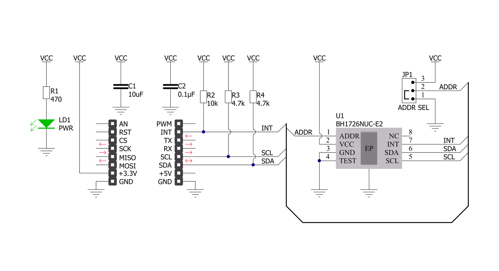
Ambient 16 Click is based on the BH1726NUC, a 16-bit digital-output ambient light sensor from Rohm Semiconductor. The BH1726NUC can detect a wide range of illuminance up to 30klx and provides excellent responsivity close to the response of human eyes. It also has stable performance over a wide temperature range and a voltage range suitable to measure the amount of the present ambient light. The BH1726NUC is designed to control the brightness in various applications based on ambient light availability, brightness for optimum visibility, and energy efficiency. This IC can change its ambient light
sensitivity to compensate for the effect of attenuation by the optical window. Adjustment is made by changing the measurement time. For example, when the transmission rate of the optical window is 1/n (measurement result becomes 1/n times if the optical window is set), the effect of the optical window is compensated by changing sensor sensitivity from default to n times. Ambient 16 Click communicates with MCU using the standard I2C 2-Wire interface to read data and configure settings, supporting Standard Mode operation with a clock frequency of 100kHz and Fast Mode up to 400kHz. Besides, the BH1726NUC
allows choosing the least significant bit (LSB) of its I2C slave address using the SMD jumper labeled ADDR SEL. It also possesses an additional interrupt signal, routed on the INT pin of the mikroBUS™ socket labeled as INT, indicating when a specific interrupt event occurs. This Click board™ can be operated only with a 3.3V logic voltage level. The board must perform appropriate logic voltage level conversion before using MCUs with different logic levels. Also, it comes equipped with a library containing functions and an example code that can be used as a reference for further development.


Features overview
Development board
EasyPIC v8 is a development board specially designed for the needs of rapid development of embedded applications. It supports many high pin count 8-bit PIC microcontrollers from Microchip, regardless of their number of pins, and a broad set of unique functions, such as the first-ever embedded debugger/programmer. The development board is well organized and designed so that the end-user has all the necessary elements, such as switches, buttons, indicators, connectors, and others, in one place. Thanks to innovative manufacturing technology, EasyPIC v8 provides a fluid and immersive working experience, allowing access anywhere and under any
circumstances at any time. Each part of the EasyPIC v8 development board contains the components necessary for the most efficient operation of the same board. In addition to the advanced integrated CODEGRIP programmer/debugger module, which offers many valuable programming/debugging options and seamless integration with the Mikroe software environment, the board also includes a clean and regulated power supply module for the development board. It can use a wide range of external power sources, including a battery, an external 12V power supply, and a power source via the USB Type-C (USB-C) connector.
Communication options such as USB-UART, USB DEVICE, and CAN are also included, including the well-established mikroBUS™ standard, two display options (graphical and character-based LCD), and several different DIP sockets. These sockets cover a wide range of 8-bit PIC MCUs, from the smallest PIC MCU devices with only eight up to forty pins. EasyPIC v8 is an integral part of the Mikroe ecosystem for rapid development. Natively supported by Mikroe software tools, it covers many aspects of prototyping and development thanks to a considerable number of different Click boards™ (over a thousand boards), the number of which is growing every day.

Microcontroller Overview
MCU Card / MCU
Architecture
PIC
MCU Memory (KB)
32
Silicon Vendor
Microchip
Pin count
40
RAM (Bytes)
2048
Used MCU Pins
mikroBUS™ mapper
Take a closer look
Click board™ Schematic
Step by step
Project assembly

Start by selecting your development board and Click board™. Begin with the EasyPIC v8 as your development board.


Track your results in real time
Application Output
1. Application Output - In Debug mode, the 'Application Output' window enables real-time data monitoring, offering direct insight into execution results. Ensure proper data display by configuring the environment correctly using the provided tutorial.

2. UART Terminal - Use the UART Terminal to monitor data transmission via a USB to UART converter, allowing direct communication between the Click board™ and your development system. Configure the baud rate and other serial settings according to your project's requirements to ensure proper functionality. For step-by-step setup instructions, refer to the provided tutorial.

3. Plot Output - The Plot feature offers a powerful way to visualize real-time sensor data, enabling trend analysis, debugging, and comparison of multiple data points. To set it up correctly, follow the provided tutorial, which includes a step-by-step example of using the Plot feature to display Click board™ readings. To use the Plot feature in your code, use the function: plot(*insert_graph_name*, variable_name);. This is a general format, and it is up to the user to replace 'insert_graph_name' with the actual graph name and 'variable_name' with the parameter to be displayed.

Software Support
Library Description
This library contains API for Ambient 16 Click driver.
Key functions:
ambient16_get_part_id- Ambient 16 get part ID functionambient16_set_gain- Ambient 16 set ADC gain functionambient16_read_data- Ambient 16 get data in lux function
Open Source
Code example
The complete application code and a ready-to-use project are available through the NECTO Studio Package Manager for direct installation in the NECTO Studio. The application code can also be found on the MIKROE GitHub account.
/*!
 * @file main.c
 * @brief Ambient16 Click example
 *
 * # Description
 * This is an example that demonstrates the use of the Ambient 16 Click board
 * by measuring illuminance and displaying the value in Lux.
 *
 * The demo application is composed of two sections :
 *
 * ## Application Init
 * Initializes I2C driver performs software reset and applies default settings.
 *
 * ## Application Task
 * Demonstrates use of Ambient 16 Click board by reading data values of DATA0 and DATA1 in Lux
 * every second, and logging it on the UART terminal.
 *
 * @author Stefan Ilic
 *
 */

#include "board.h"
#include "log.h"
#include "ambient16.h"

static ambient16_t ambient16;
static log_t logger;
static float data0;
static float data1;

void application_init ( void )
{
    log_cfg_t log_cfg;  /**< Logger config object. */
    ambient16_cfg_t ambient16_cfg;  /**< Click config object. */

    /**
     * Logger initialization.
     * Default baud rate: 115200
     * Default log level: LOG_LEVEL_DEBUG
     * @note If USB_UART_RX and USB_UART_TX
     * are defined as HAL_PIN_NC, you will
     * need to define them manually for log to work.
     * See @b LOG_MAP_USB_UART macro definition for detailed explanation.
     */
    LOG_MAP_USB_UART( log_cfg );
    log_init( &logger, &log_cfg );
    log_info( &logger, " Application Init " );

    // Click initialization.
    ambient16_cfg_setup( &ambient16_cfg );
    AMBIENT16_MAP_MIKROBUS( ambient16_cfg, MIKROBUS_1 );
    if ( I2C_MASTER_ERROR == ambient16_init( &ambient16, &ambient16_cfg ) )
    {
        log_error( &logger, " Communication init." );
        for ( ; ; );
    }

    if ( AMBIENT16_ERROR == ambient16_default_cfg ( &ambient16 ) )
    {
        log_error( &logger, " Default configuration." );
        for ( ; ; );
    }

    uint8_t id;
    ambient16_get_part_id( &ambient16, &id );

    log_printf( &logger, "- - - - - - - - - - - - -\r\n" );
    log_printf( &logger, " Part ID = 0x%.2X \r\n", ( uint16_t ) id );
    log_printf( &logger, "- - - - - - - - - - - - -\r\n" );
    Delay_ms ( 500 );
    log_info( &logger, " Application Task " );
    log_printf( &logger, "- - - - - - - - - - - - -\r\n" );
}

void application_task ( void )
{
    ambient16_read_data( &ambient16, &data0, &data1 );

    log_printf( &logger, " DATA 0 = %.2f lx    \r\n", data0 );
    log_printf( &logger, " DATA 1 = %.2f lx    \r\n", data1 );
    log_printf( &logger, "- - - - - - - - - - -\r\n" );
    Delay_ms ( 1000 );
}

int main ( void )
{
    /* Do not remove this line or clock might not be set correctly. */
    #ifdef PREINIT_SUPPORTED
    preinit();
    #endif

    application_init( );

    for ( ; ; )
    {
        application_task( );
    }

    return 0;
}

// ------------------------------------------------------------------------ END


