Achieve precise and accurate tracking of the device's location in real-time with DWM3001 and PIC18LF45K22
Fully-integrated UWB transceiver

Published Dec 11, 2023
Click board™
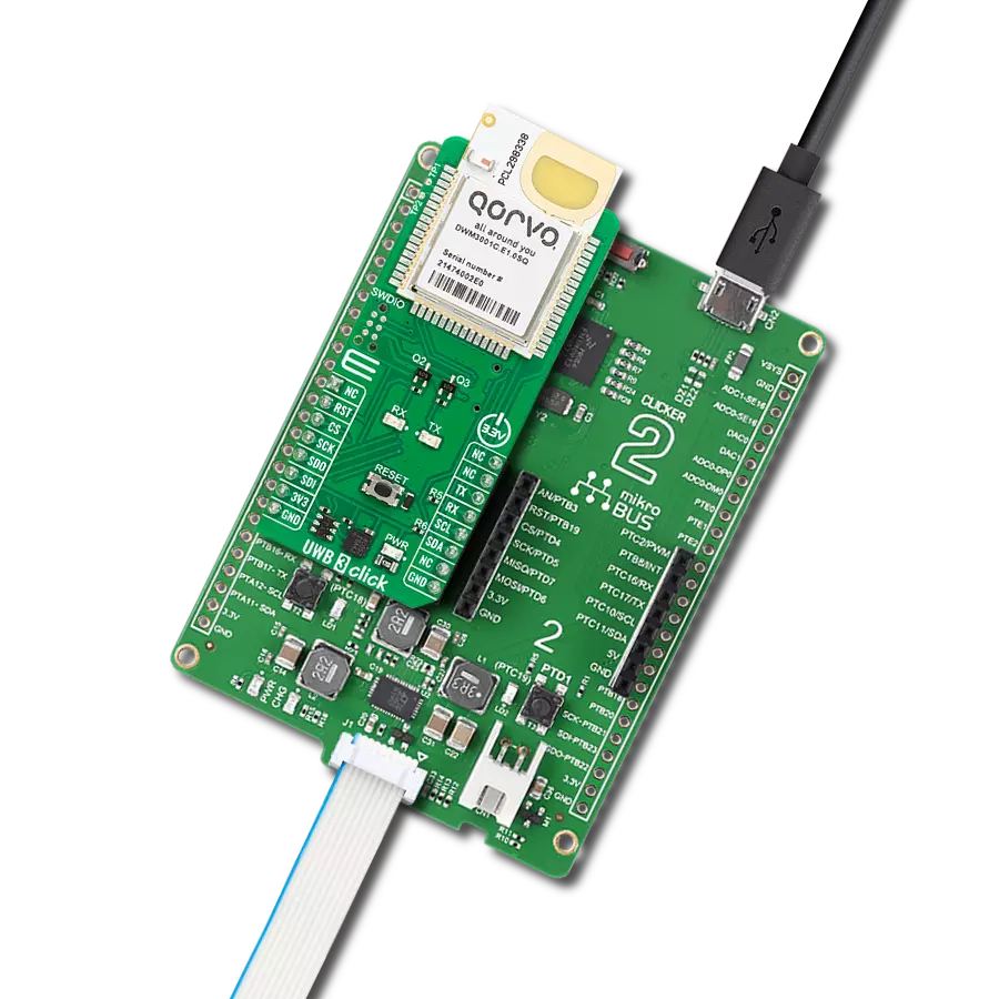
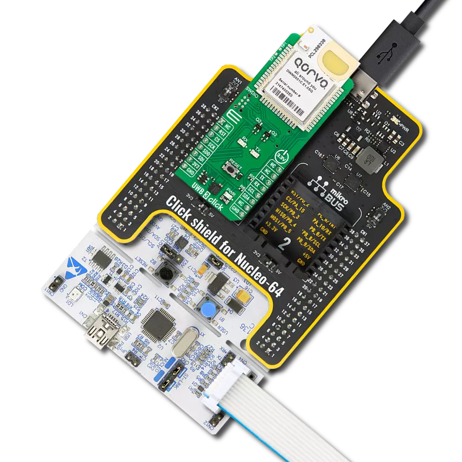
UWB 3 Click
Dev. board
EasyPIC v8
Compiler
NECTO Studio
MCU
PIC18LF45K22
It's useful for creating systems that require precise location tracking, like tracking the location of objects or devices in real-time.
A
A
Hardware Overview
How does it work?
UWB 3 Click is based on the DWM3001, a fully integrated UWB transceiver module from Qorvo. The module can be used in two-way ranging and TDoA applications. It is designed to comply with the FiRa™ PHY and MAC specifications, enabling interoperability with other FiRa™-compliant devices. It supports channels 5 (6.5GHz) and 9 (8GHz) and data rates of 850Kbps up to 6.8Mbps with a maximum packet length of 1023 bytes for high data throughput applications. Besides the planar UWB printed antenna, there is also a Bluetooth chip antenna for an onboard Nordic Cortex-M4 32-bit MCU with 64MHz clock speed for utilizing a BLE radio transceiver. This Nordic MCU is the brain of the module. The nRF52833 has advanced on-chip interfaces, such as NFC-A and USB 2.0 (full-speed 12Mbps), available on UWB 3
Click in a USB C form. The DWM3001 UWB transceiver also incorporates the LIS12DH, a low-power three-axis linear accelerometer from STMicroelectronics. It is necessary as RTLS tags commonly use accelerometers to initiate UWB ranging only when a tag moves so that battery life can be extended by staying in the lowest power mode by default. Near-field communication type 2 (NFC-A) can be used by adding an NFC antenna to the TP1 and TP2 pads. UWB 3 Click can use a standard 2-Wire UART interface of the nRF52833 to communicate with the host MCU with commonly used UART RX and TX pins and baud rates of 115200bps. There are RX and TX LEDs for visual presentation of data flow. It can also use a 4-Wire SPI serial interface on 32MHz for communication. The I2C interface, besides the communication
with the Nordic MCU, allows you to read the data from the accelerometer. It should be noted that the current module firmware does not support the SPI and I2C serial interfaces; these interfaces are reserved for future use. You can reset the module over the RST pin but also over the RESET button. The nRF52833 firmware can be updated over the SWDIO 6-pin needle connector. This Click board™ can be operated only with a 3.3V logic voltage level. The board must perform appropriate logic voltage level conversion before using MCUs with different logic levels. Also, this Click board™ comes equipped with a library containing easy-to-use functions and an example code that can be used as a reference for further development.

Features overview
Development board
EasyPIC v8 is a development board specially designed for the needs of rapid development of embedded applications. It supports many high pin count 8-bit PIC microcontrollers from Microchip, regardless of their number of pins, and a broad set of unique functions, such as the first-ever embedded debugger/programmer. The development board is well organized and designed so that the end-user has all the necessary elements, such as switches, buttons, indicators, connectors, and others, in one place. Thanks to innovative manufacturing technology, EasyPIC v8 provides a fluid and immersive working experience, allowing access anywhere and under any
circumstances at any time. Each part of the EasyPIC v8 development board contains the components necessary for the most efficient operation of the same board. In addition to the advanced integrated CODEGRIP programmer/debugger module, which offers many valuable programming/debugging options and seamless integration with the Mikroe software environment, the board also includes a clean and regulated power supply module for the development board. It can use a wide range of external power sources, including a battery, an external 12V power supply, and a power source via the USB Type-C (USB-C) connector.
Communication options such as USB-UART, USB DEVICE, and CAN are also included, including the well-established mikroBUS™ standard, two display options (graphical and character-based LCD), and several different DIP sockets. These sockets cover a wide range of 8-bit PIC MCUs, from the smallest PIC MCU devices with only eight up to forty pins. EasyPIC v8 is an integral part of the Mikroe ecosystem for rapid development. Natively supported by Mikroe software tools, it covers many aspects of prototyping and development thanks to a considerable number of different Click boards™ (over a thousand boards), the number of which is growing every day.

Microcontroller Overview
MCU Card / MCU
Architecture
PIC
MCU Memory (KB)
32
Silicon Vendor
Microchip
Pin count
40
RAM (Bytes)
1536
Used MCU Pins
mikroBUS™ mapper
Take a closer look
Click board™ Schematic

Step by step
Project assembly

Start by selecting your development board and Click board™. Begin with the EasyPIC v8 as your development board.


Software Support
Library Description
This library contains API for UWB 3 Click driver.
Key functions:
uwb3_send_cmd- This function sends a specified command to the click module.uwb3_send_cmd_with_parameter- This function sends a command with specified parameter to the click module.uwb3_reset_device- This function resets the device by toggling the RST pin state.
Open Source
Code example
The complete application code and a ready-to-use project are available through the NECTO Studio Package Manager for direct installation in the NECTO Studio. The application code can also be found on the MIKROE GitHub account.
/*!
 * @file main.c
 * @brief UWB 3 Click Example.
 *
 * # Description
 * This example demonstrates the use of an UWB 3 Click board by showing
 * the communication between the two Click boards.
 *
 * The demo application is composed of two sections :
 *
 * ## Application Init
 * Initializes the driver and configures the Click board for the selected
 * application mode.
 *
 * ## Application Task
 * Reads and processes all incoming ranging block messages and displays them
 * on the USB UART. One Click board should be configured to initiator mode and
 * the others to responder 1 or 2. The initiator Click displays the address
 * and distance of each responder nodes, while the responder Click boards displays
 * the address and distance of the initiator Click board.
 *
 * ## Additional Function
 * - static void uwb3_clear_app_buf ( void )
 * - static void uwb3_log_app_buf ( void )
 * - static err_t uwb3_process ( uwb3_t *ctx )
 * - static err_t uwb3_display_response ( uwb3_t *ctx )
 * - static err_t uwb3_parse_ranging_block ( void )
 *
 * @author Stefan Filipovic
 *
 */

#include "board.h"
#include "log.h"
#include "uwb3.h"

// Demo aplication selection macros
#define APP_INITIATOR               0
#define APP_RESPONDER_1             1
#define APP_RESPONDER_2             2
#define DEMO_APP                    APP_INITIATOR

/** INITF/RESPF parameter list and default value
 * Order    Config Param            Default value           Description
 * #1       RFRAME BPRF             4                       RFRAME BRFF set as per FiRa spec:
 *                                                          4 - SP3 SFD4Z, 6 - SP3 SFD4A
 * #2       RSTU slot duration      2400                    Duration of the slot in RSTU time units.
 *                                                          1ms = 1200 RSTU
 * #3       Block duration ms       200                     Duration of the FiRa ranging block in ms
 * #4       Round duration slots    25                      Duration of the FiRa ranging round inside
 *                                                          the block
 * #5       Ranging Round usage     2                       0 - Not used, 1 - SS-TWR, 2 - DS-TWR
 * #6       Session ID              42                      Session ID
 * #7       vupper64                01:02:03:04:05:06:07:08 Eight hexadecimal numbers, represented
 *                                                          static part of the STS in FiRa standard,
 *                                                          Hex values separated by ":"
 * #8       Multi node mode         0                       0 for unicast, 1 for multi-node configuration
 * #9       Round hopping           0                       0 for no round hopping, 1 for round hopping
 * #10      Initiator address       0                       Address of FiRa Initiator, Decimal value 0-65535
 * #11      Responder address       1                       Address of responder or set of addresses for
 *                                                          multiple responders, Decimal value 0-65535
 */
#define INITIATOR_CONFIG            "4 2400 200 25 2 42 01:02:03:04:05:06:07:08 1 0 0 1 2"
#define RESPONDER_1_CONFIG          "4 2400 200 25 2 42 01:02:03:04:05:06:07:08 1 0 0 1"
#define RESPONDER_2_CONFIG          "4 2400 200 25 2 42 01:02:03:04:05:06:07:08 1 0 0 2"

// Application buffer size
#define APP_BUFFER_SIZE             800
#define PROCESS_BUFFER_SIZE         200

static uwb3_t uwb3;
static log_t logger;

static uint8_t app_buf[ APP_BUFFER_SIZE ] = { 0 };
static int32_t app_buf_len = 0;

/**
 * @brief UWB 3 clearing application buffer.
 * @details This function clears memory of application buffer and reset its length.
 * @note None.
 */
static void uwb3_clear_app_buf ( void );

/**
 * @brief UWB 3 log application buffer.
 * @details This function logs data from application buffer to USB UART.
 * @note None.
 */
static void uwb3_log_app_buf ( void );

/**
 * @brief UWB 3 data reading function.
 * @details This function reads data from device and concatenates data to application buffer.
 * @param[in] ctx : Click context object.
 * See #uwb3_t object definition for detailed explanation.
 * @return @li @c  0 - Read some data.
 *         @li @c -1 - Nothing is read.
 * See #err_t definition for detailed explanation.
 * @note None.
 */
static err_t uwb3_process ( uwb3_t *ctx );

/**
 * @brief UWB 3 display response function.
 * @details This function reads and displays the response to previously sent command.
 * @param[in] ctx : Click context object.
 * See #uwb3_t object definition for detailed explanation.
 * @return @li @c  0 - OK response.
 *         @li @c -2 - Timeout error.
 * See #err_t definition for detailed explanation.
 */
static err_t uwb3_display_response ( uwb3_t *ctx );

/**
 * @brief UWB 3 parse ranging block function.
 * @details This function parses the ranging block results from application buffer and
 * displays it to the USB UART.
 * @return @li @c  0 - Ranging block data parsed successfully.
 *         @li @c -1 - No valid ranging block data in application buffer.
 * See #err_t definition for detailed explanation.
 */
static err_t uwb3_parse_ranging_block ( void );

void application_init ( void )
{
    log_cfg_t log_cfg;  /**< Logger config object. */
    uwb3_cfg_t uwb3_cfg;  /**< Click config object. */

    /**
     * Logger initialization.
     * Default baud rate: 115200
     * Default log level: LOG_LEVEL_DEBUG
     * @note If USB_UART_RX and USB_UART_TX
     * are defined as HAL_PIN_NC, you will
     * need to define them manually for log to work.
     * See @b LOG_MAP_USB_UART macro definition for detailed explanation.
     */
    LOG_MAP_USB_UART( log_cfg );
    log_init( &logger, &log_cfg );
    log_info( &logger, " Application Init " );

    // Click initialization.
    uwb3_cfg_setup( &uwb3_cfg );
    UWB3_MAP_MIKROBUS( uwb3_cfg, MIKROBUS_1 );
    if ( UART_ERROR == uwb3_init( &uwb3, &uwb3_cfg ) )
    {
        log_error( &logger, " Communication init." );
        for ( ; ; );
    }
    // Clear buffers
    uwb3_process( &uwb3 );
    uwb3_clear_app_buf( );

    // Switch to stop mode
    uwb3_send_cmd ( &uwb3, UWB3_CMD_STOP );
    uwb3_display_response ( &uwb3 );
    Delay_ms ( 1000 );

#if ( DEMO_APP == APP_RESPONDER_1 )
    uwb3_send_cmd_with_parameter ( &uwb3, UWB3_CMD_RESPF, RESPONDER_1_CONFIG );
    uwb3_display_response ( &uwb3 );
    log_printf( &logger, "Application Mode: Responder 1\r\n" );
#elif ( DEMO_APP == APP_RESPONDER_2 )
    uwb3_send_cmd_with_parameter ( &uwb3, UWB3_CMD_RESPF, RESPONDER_2_CONFIG );
    uwb3_display_response ( &uwb3 );
    log_printf( &logger, "Application Mode: Responder 2\r\n" );
#else
    uwb3_send_cmd_with_parameter ( &uwb3, UWB3_CMD_INITF, INITIATOR_CONFIG );
    uwb3_display_response ( &uwb3 );
    log_printf( &logger, "Application Mode: Initiator\r\n" );
#endif

    uwb3_clear_app_buf( );
    log_info( &logger, " Application Task " );
}

void application_task ( void )
{
    if ( UWB3_OK == uwb3_process( &uwb3 ) )
    {
        if ( UWB3_OK == uwb3_parse_ranging_block ( ) )
        {
            uwb3_clear_app_buf( );
        }
    }
}

int main ( void )
{
    /* Do not remove this line or clock might not be set correctly. */
    #ifdef PREINIT_SUPPORTED
    preinit();
    #endif

    application_init( );

    for ( ; ; )
    {
        application_task( );
    }

    return 0;
}

static void uwb3_clear_app_buf ( void )
{
    memset( app_buf, 0, app_buf_len );
    app_buf_len = 0;
}

static void uwb3_log_app_buf ( void )
{
    for ( int32_t buf_cnt = 0; buf_cnt < app_buf_len; buf_cnt++ )
    {
        log_printf( &logger, "%c", app_buf[ buf_cnt ] );
    }
}

static err_t uwb3_process ( uwb3_t *ctx )
{
    uint8_t rx_buf[ PROCESS_BUFFER_SIZE ] = { 0 };
    int32_t overflow_bytes = 0;
    int32_t rx_cnt = 0;
    int32_t rx_size = uwb3_generic_read( ctx, rx_buf, PROCESS_BUFFER_SIZE );
    if ( ( rx_size > 0 ) && ( rx_size <= APP_BUFFER_SIZE ) )
    {
        if ( ( app_buf_len + rx_size ) > APP_BUFFER_SIZE )
        {
            overflow_bytes = ( app_buf_len + rx_size ) - APP_BUFFER_SIZE;
            app_buf_len = APP_BUFFER_SIZE - rx_size;
            memmove ( app_buf, &app_buf[ overflow_bytes ], app_buf_len );
            memset ( &app_buf[ app_buf_len ], 0, overflow_bytes );
        }
        for ( rx_cnt = 0; rx_cnt < rx_size; rx_cnt++ )
        {
            if ( rx_buf[ rx_cnt ] )
            {
                app_buf[ app_buf_len++ ] = rx_buf[ rx_cnt ];
            }
        }
        return UWB3_OK;
    }
    return UWB3_ERROR;
}

static err_t uwb3_display_response ( uwb3_t *ctx )
{
    uint32_t timeout_cnt = 0;
    uint32_t timeout = 10000;
    uwb3_clear_app_buf( );
    uwb3_process( ctx );
    while ( ( 0 == strstr( app_buf, UWB3_RSP_OK ) ) &&
            ( 0 == strstr( app_buf, UWB3_RSP_ERROR ) ) )
    {
        uwb3_process( ctx );
        if ( timeout_cnt++ > timeout )
        {
            uwb3_clear_app_buf( );
            log_error( &logger, " Timeout!" );
            return UWB3_ERROR_TIMEOUT;
        }
        Delay_ms ( 1 );
    }
    Delay_ms ( 100 );
    uwb3_process( ctx );
    uwb3_log_app_buf ( );
    log_printf( &logger, "--------------------------\r\n" );
    return UWB3_OK;
}

static err_t uwb3_parse_ranging_block ( void )
{
    uint8_t * __generic_ptr start_block_ptr = NULL;
    uint8_t * __generic_ptr end_block_ptr = NULL;
    uint8_t * __generic_ptr results_ptr = NULL;
    start_block_ptr = &app_buf[ 0 ];
    for ( ; ; )
    {
        start_block_ptr = strstr( start_block_ptr, "\"Block\"" );
        if ( !start_block_ptr )
        {
            return UWB3_ERROR;
        }
        end_block_ptr = strstr( start_block_ptr, "\r\n" );
        if ( !end_block_ptr )
        {
            return UWB3_ERROR;
        }
        results_ptr = strstr( start_block_ptr, "\"Status\":\"Ok\"" );
        if ( results_ptr && ( ( uint32_t ) results_ptr < ( uint32_t ) end_block_ptr ) )
        {
            log_printf( &logger, "######### " );
            while ( ',' != *start_block_ptr )
            {
                log_printf( &logger, "%c", *start_block_ptr );
                start_block_ptr++;
            }
            log_printf( &logger, " #########\r\n\n" );

            while ( results_ptr && ( ( uint32_t ) results_ptr < ( uint32_t ) end_block_ptr ) )
            {
                // Display node address
                results_ptr -= 16;
                while ( ',' != *results_ptr )
                {
                    log_printf( &logger, "%c", *results_ptr );
                    results_ptr++;
                }
                log_printf( &logger, "\r\n" );
                // Display node distance
                results_ptr = strstr( results_ptr, "\"D_cm\"" );
                while ( ',' != *results_ptr )
                {
                    log_printf( &logger, "%c", *results_ptr );
                    results_ptr++;
                }
                log_printf( &logger, "\r\n\n" );
                results_ptr = strstr( results_ptr, "\"Status\":\"Ok\"" );
            }
            return UWB3_OK;
        }
        start_block_ptr = end_block_ptr;
    }
}

// ------------------------------------------------------------------------ END