Experience the perfect climate right at your fingertips, thanks to HTU31D and PIC18LF45K50
Breathe easy with our climate wizardry

Published Nov 11, 2023
Click board™
Temp&Hum 14 Click
Dev. board
EasyPIC v8
Compiler
NECTO Studio
MCU
PIC18LF45K50
Count on our climate solution to provide valuable insights into temperature and humidity, contributing to a smarter and more sustainable future.
A
A
Hardware Overview
How does it work?
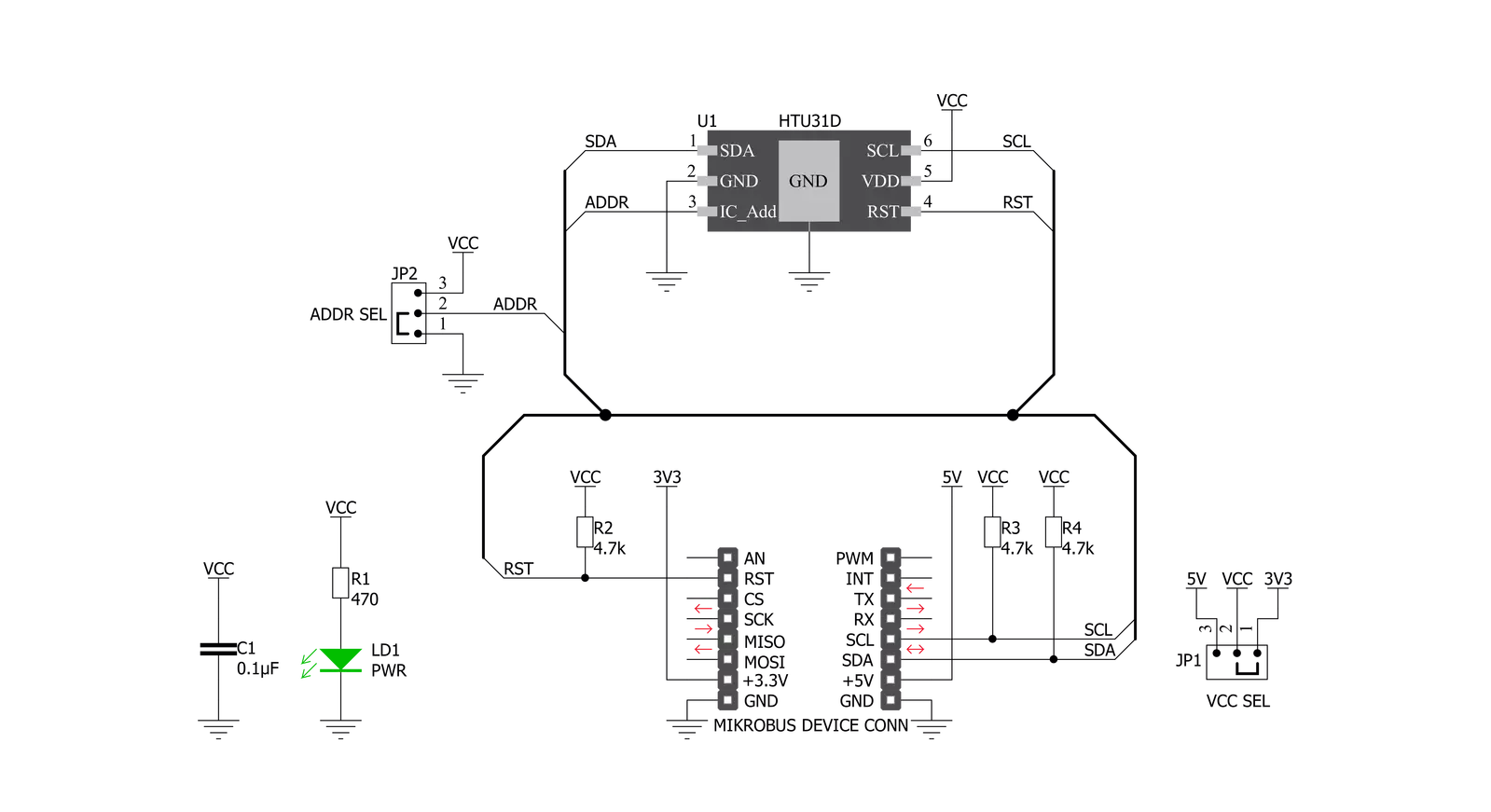
Temp&Hum 14 Click is based on the HTU31D, a digital relative humidity sensor with temperature output from TE Connectivity. Both sensors inside the HTU31D are individually calibrated, compensated, and tested. The humidity can be measured within a range of 0 to 100 %RH, while the temperature sensor is designed for a range of -40 to 125 °C. The typical accuracy for humidity is ± 2 %RH in the measuring range of 20 up to 100 %RH at ambient temperature and ±0.2 °C for temperature between 0 - 100 °C with power consumption down to 3.78μW. This Click board™, an I2C configurable environmental sensor, is characterized by high reliability and full interchangeability with no calibration required in standard conditions. It has a quick recovery time after long periods in the saturation phase, low power
consumption, and fast response time. Also, this sensor provides sustained performance even when exposed to extreme temperatures up to 125°C and humidity environments. Temp & Hum 14 Click communicates with MCU using the standard I2C 2-Wire interface with a maximum frequency 10MHz. The HTU31D can answer 2 I2C addresses and allows the choice of the least significant bit (LSB) by positioning SMD jumpers labeled as ADDR SEL to an appropriate position marked as 0 and 1. In addition to this feature, this Click board™ also contains additional functionality routed to the RST pin on the mikroBUS™ socket. The RST pin can generate a sensor reset with a minimum pulse duration of 1 μs required to trigger this function. The HTU31D also offers a diagnostic register that can be used to check whether
the values for humidity and temperature are outside the specified range. The CRC check (Cyclic Redundancy Check) ensures secure data transmission. The humidity and temperature signal response time, as well as the recovery time (after complete condensation), are within a range of a few seconds. This Click board™ can operate with either 3.3V or 5V logic voltage levels selected via the VCC SEL jumper. This way, both 3.3V and 5V capable MCUs can use the communication lines properly. Also, this Click board™ comes equipped with a library containing easy-to-use functions and an example code that can be used as a reference for further development.

Features overview
Development board
EasyPIC v8 is a development board specially designed for the needs of rapid development of embedded applications. It supports many high pin count 8-bit PIC microcontrollers from Microchip, regardless of their number of pins, and a broad set of unique functions, such as the first-ever embedded debugger/programmer. The development board is well organized and designed so that the end-user has all the necessary elements, such as switches, buttons, indicators, connectors, and others, in one place. Thanks to innovative manufacturing technology, EasyPIC v8 provides a fluid and immersive working experience, allowing access anywhere and under any
circumstances at any time. Each part of the EasyPIC v8 development board contains the components necessary for the most efficient operation of the same board. In addition to the advanced integrated CODEGRIP programmer/debugger module, which offers many valuable programming/debugging options and seamless integration with the Mikroe software environment, the board also includes a clean and regulated power supply module for the development board. It can use a wide range of external power sources, including a battery, an external 12V power supply, and a power source via the USB Type-C (USB-C) connector.
Communication options such as USB-UART, USB DEVICE, and CAN are also included, including the well-established mikroBUS™ standard, two display options (graphical and character-based LCD), and several different DIP sockets. These sockets cover a wide range of 8-bit PIC MCUs, from the smallest PIC MCU devices with only eight up to forty pins. EasyPIC v8 is an integral part of the Mikroe ecosystem for rapid development. Natively supported by Mikroe software tools, it covers many aspects of prototyping and development thanks to a considerable number of different Click boards™ (over a thousand boards), the number of which is growing every day.

Microcontroller Overview
MCU Card / MCU
Architecture
PIC
MCU Memory (KB)
32
Silicon Vendor
Microchip
Pin count
40
RAM (Bytes)
2048
Used MCU Pins
mikroBUS™ mapper
Take a closer look
Click board™ Schematic
Step by step
Project assembly

Start by selecting your development board and Click board™. Begin with the EasyPIC v8 as your development board.


Software Support
Library Description
This library contains API for Temp&Hum 14 Click driver.
Key functions:
temphum14_set_conversion- The function set conversion a single temperature and humidity conversion and select data resolution to the HTU31Dtemphum14_read_t_and_rh- The function read temperature and humidity data of the HTU31Dtemphum14_get_temp_and_hum- The function get temperature and humidity value of the HTU31D
Open Source
Code example
The complete application code and a ready-to-use project are available through the NECTO Studio Package Manager for direct installation in the NECTO Studio. The application code can also be found on the MIKROE GitHub account.
/*!
 * @file main.c
 * @brief TempHum14 Click example
 *
 * # Description
 * This is an example that demonstrates the use of the Temp-Hum 14 Click board.
 * Temp-Hum 14 Click board can be used to measure temperature
 * and relative humidity.
 * All data logs write on USB uart changes every 3 sec.
 *
 * The demo application is composed of two sections :
 *
 * ## Application Init
 * Initialization driver enables I2C, and
 * hardware reset the device and read the serial number.
 *
 * ## Application Task
 * Reading temperature and humidity, and loging it on the USB uart.
 *
 * @author Stefan Ilic
 *
 */

#include "board.h"
#include "log.h"
#include "temphum14.h"

static temphum14_t temphum14;
static log_t logger;
static temphum14_diagn_t status_data;
static float temperature;
static float humidity;
uint32_t ser_numb;

void display_diagnostic ( void ) {
    log_printf( &logger, "-----------------------------\r\n" );
    log_printf( &logger, "\r\n NVM Error        :" );
    if ( status_data.nvm_error == TEMPHUM14_STATUS_ON ) {
        log_printf( &logger, " Error \r\n" );
    } else {
        log_printf( &logger, " No Error \r\n" );
    }

    log_printf( &logger, "\r\n Humidity U/O     :" );
    if ( status_data.hum_un_over == TEMPHUM14_STATUS_ON ) {
        log_printf( &logger, " Under/Overrun \r\n" );
    } else {
        log_printf( &logger, " No Error \r\n" );
    }

    log_printf( &logger, "\r\n Humidity Error   :" );
    if ( status_data.hum_h_err == TEMPHUM14_STATUS_ON ) {
        log_printf( &logger, " Below -10%% RH \r\n" );
    } else if ( status_data.hum_l_err == TEMPHUM14_STATUS_ON ) {
        log_printf( &logger, " Above 120%% RH \r\n" );
    } else {
        log_printf( &logger, " No Error \r\n" );
    }

    log_printf( &logger, "\r\n Temperature U/O  :" );
    if ( status_data.temp_un_over == TEMPHUM14_STATUS_ON ) {
        log_printf( &logger, " Under/Overrun \r\n" );
    } else {
        log_printf( &logger, " No Error \r\n" );
    }

    log_printf( &logger, "\r\n Temperature Error:" );
    if ( status_data.temp_h_err == TEMPHUM14_STATUS_ON ) {
        log_printf( &logger, " Below -50 C \r\n" );
    } else if ( status_data.temp_l_err == TEMPHUM14_STATUS_ON ) {
        log_printf( &logger, " Above 150 C \r\n" );
    } else {
        log_printf( &logger, " No Error \r\n" );
    }

    log_printf( &logger, "\r\n Heater Status    :" );
    if ( status_data.heater_on == TEMPHUM14_STATUS_ON ) {
        log_printf( &logger, " ON \r\n" );
    } else {
        log_printf( &logger, " OFF \r\n" );
    }

    log_printf( &logger, "-----------------------------\r\n" );
}

void application_init ( void ) {
    log_cfg_t log_cfg;  /**< Logger config object. */
    temphum14_cfg_t temphum14_cfg;  /**< Click config object. */

    /**
     * Logger initialization.
     * Default baud rate: 115200
     * Default log level: LOG_LEVEL_DEBUG
     * @note If USB_UART_RX and USB_UART_TX
     * are defined as HAL_PIN_NC, you will
     * need to define them manually for log to work.
     * See @b LOG_MAP_USB_UART macro definition for detailed explanation.
     */
    LOG_MAP_USB_UART( log_cfg );
    log_init( &logger, &log_cfg );
    log_printf( &logger, "-----------------------------\r\n" );
    log_info( &logger, " Application Init " );
    log_printf( &logger, "-----------------------------\r\n" );

    // Click initialization.
    temphum14_cfg_setup( &temphum14_cfg );
    TEMPHUM14_MAP_MIKROBUS( temphum14_cfg, MIKROBUS_1 );
    err_t init_flag = temphum14_init( &temphum14, &temphum14_cfg );
    if ( I2C_MASTER_ERROR == init_flag ) {
        log_error( &logger, " Application Init Error. " );
        log_info( &logger, " Please, run program again... " );

        for ( ; ; );
    }
    Delay_ms ( 100 );
    log_printf( &logger, "-----------------------------\r\n" );
    log_printf( &logger, " Hardware Reset \r\n" );
    temphum14_hw_reset( &temphum14 );
    Delay_ms ( 100 );

    ser_numb = temphum14_get_serial_number( &temphum14 );
    log_printf( &logger, "-----------------------------\r\n" );
    log_printf( &logger, " Serial Number : %lu \r\n", ser_numb );
    log_printf( &logger, "-----------------------------\r\n" );
    log_printf( &logger, " Software Reset \r\n" );
    temphum14_soft_reset( &temphum14 );
    Delay_ms ( 100 );

    temphum14_get_diagnostic( &temphum14, &status_data );
    Delay_ms ( 100 );

    display_diagnostic( );
    Delay_ms ( 100 );

    log_info( &logger, " Application Task " );
    log_printf( &logger, "-----------------------------\r\n" );
}

void application_task ( void ) {
    temphum14_set_conversion( &temphum14, TEMPHUM14_CONVERSION_HUM_OSR_0_020, TEMPHUM14_CONVERSION_TEMP_0_040 );
    Delay_ms ( 10 );

    temphum14_get_temp_and_hum( &temphum14, &temperature, &humidity );
    Delay_ms ( 10 );

    log_printf( &logger, "  Temperature : %.2f C \r\n", temperature );
    log_printf( &logger, "  Humidity    : %.2f %% \r\n", humidity );
    log_printf( &logger, "-----------------------------\r\n" );
    Delay_ms ( 1000 );
    Delay_ms ( 1000 );
    Delay_ms ( 1000 );
}

int main ( void )
{
    /* Do not remove this line or clock might not be set correctly. */
    #ifdef PREINIT_SUPPORTED
    preinit();
    #endif

    application_init( );

    for ( ; ; )
    {
        application_task( );
    }

    return 0;
}

// ------------------------------------------------------------------------ END
Additional Support
Resources
Category:Temperature & humidity


