Deliver an immersive audio experience with INA1620 and PIC18LF47K42
Feel the pulse, hear the difference!

Published Nov 11, 2023
Click board™
Headphone AMP 3 Click
Dev. board
EasyPIC v8
Compiler
NECTO Studio
MCU
PIC18LF47K42
Experience audio like never before – our sound amplifier is engineered to capture the nuances of sound, providing a richer, more immersive auditory journey.
A
A
Hardware Overview
How does it work?
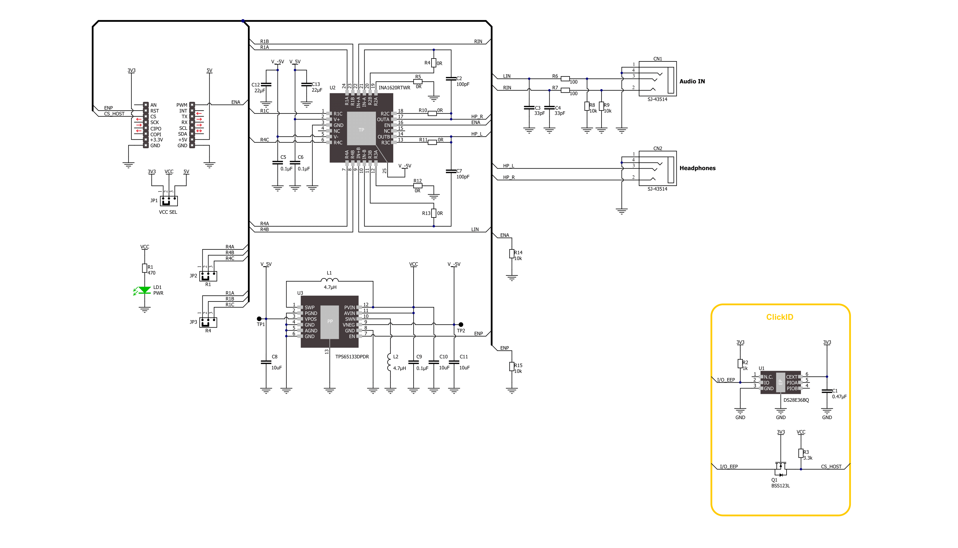
Headphone AMP 3 Click is based on the INA1620, a high-fidelity audio operational amplifier with integrated thin-film resistors and EMI filters from Texas Instruments. The amplifier has a high slew rate, high capacitive-load drive capability, high open-loop gain, low quiescent current per channel, low-power shutdown mode, and thermal shutdown. The internal amplifiers use a unique topology to deliver high output current with extremely low distortion while consuming minimal supply current. The amplifier input pins of the INA1620 are protected from excessive differential voltage with back-to-back diodes; thus, in most applications, the inputs will have no consequences. The INA1620 has two functional modes: a Shutdown and an Enabled mode. In Shutdown mode, the INA1620 will have minimal power consumption. However, applying signals to the output while in Shutdown mode will parasitically power the output stage of the audio
amplifier. While in Enabled mode, the INA1620 uses a few tricks to clean things up. The INA1620 uses efficient electromagnetic interference (EMI) rejection as an immunity to change in offset, thus having a higher EMIRR. Onboard, there are two 3.5mm audio connectors for connecting the audio source and headphones. The INA1620 uses positive and negative power supplies; on this Click board™, +5V and -5V power supplies are provided by the TPS65133, a ±5V, 250mA dual output power supply from Texas Instruments. The TPS65133 provides fixed positive and negative 5V with ±1% output voltage accuracy and high efficiency. It also includes a boost converter that allows a 3.3V power supply from the mikroBUS™ socket to be used. The INA1620 has integrated thin-film resistors in four blocks. You can use blocks 1 and 4 to create very high-performance audio circuit configurations. Blocks 2 and 3 are already used and configured in a circuit of this Click board™. All
resistors are of 1K, where all A and C are internally connected to a B point. The Headphone AMP 3 Click comes with jumpers to set those configurations. Points a trace connects R1B and R4B with the appropriate A points. Cut the trace with a sharp knife and solder jumper resistors to connect B points to C. The Headphone AMP 3 Click board uses two enable pins as its only connection with the host MCU. The ENA pin enables the INA1620 with a logic HIGH, as the pin is pulled LOW. The ENP is used similarly to enable the TPS65133 boost and buck-boost converter with a logic HIGH as the pin is pulled down. This Click board™ can operate with either 3.3V or 5V logic voltage levels selected via the VCC SEL jumper. This way, both 3.3V and 5V capable MCUs can use the communication lines properly. Also, this Click board™ comes equipped with a library containing easy-to-use functions and an example code that can be used for further development.

Features overview
Development board
EasyPIC v8 is a development board specially designed for the needs of rapid development of embedded applications. It supports many high pin count 8-bit PIC microcontrollers from Microchip, regardless of their number of pins, and a broad set of unique functions, such as the first-ever embedded debugger/programmer. The development board is well organized and designed so that the end-user has all the necessary elements, such as switches, buttons, indicators, connectors, and others, in one place. Thanks to innovative manufacturing technology, EasyPIC v8 provides a fluid and immersive working experience, allowing access anywhere and under any
circumstances at any time. Each part of the EasyPIC v8 development board contains the components necessary for the most efficient operation of the same board. In addition to the advanced integrated CODEGRIP programmer/debugger module, which offers many valuable programming/debugging options and seamless integration with the Mikroe software environment, the board also includes a clean and regulated power supply module for the development board. It can use a wide range of external power sources, including a battery, an external 12V power supply, and a power source via the USB Type-C (USB-C) connector.
Communication options such as USB-UART, USB DEVICE, and CAN are also included, including the well-established mikroBUS™ standard, two display options (graphical and character-based LCD), and several different DIP sockets. These sockets cover a wide range of 8-bit PIC MCUs, from the smallest PIC MCU devices with only eight up to forty pins. EasyPIC v8 is an integral part of the Mikroe ecosystem for rapid development. Natively supported by Mikroe software tools, it covers many aspects of prototyping and development thanks to a considerable number of different Click boards™ (over a thousand boards), the number of which is growing every day.

Microcontroller Overview
MCU Card / MCU
Architecture
PIC
MCU Memory (KB)
128
Silicon Vendor
Microchip
Pin count
40
RAM (Bytes)
8192
You complete me!
Accessories
These standard small stereo earphones offer a high-quality listening experience with their top-notch stereo cable and connector. Designed for universal compatibility, they effortlessly connect to all MIKROE mikromedia and multimedia boards, making them an ideal choice for your electronic projects. With a rated power of 100mW, the earphones provide crisp audio across a broad frequency range from 20Hz to 20kHz. They boast a sensitivity of 100 ± 5dB and an impedance of 32Ω ± 15%, ensuring optimal sound quality. The Φ15mm speaker delivers clear and immersive audio. Cost-effective and versatile, these earphones are perfect for testing your prototype devices, offering an affordable and reliable audio solution to complement your projects.

Used MCU Pins
mikroBUS™ mapper
Take a closer look
Click board™ Schematic
Step by step
Project assembly

Start by selecting your development board and Click board™. Begin with the EasyPIC v8 as your development board.


Software Support
Library Description
This library contains API for Headphone AMP 3 Click driver.
Key functions:
headphoneamp3_enable_power- Headphone AMP 3 power pin setting function.headphoneamp3_enable_amp- Headphone AMP 3 amp pin setting function.
Open Source
Code example
The complete application code and a ready-to-use project are available through the NECTO Studio Package Manager for direct installation in the NECTO Studio. The application code can also be found on the MIKROE GitHub account.
/*!
 * @file main.c
 * @brief Headphone AMP 3 Click Example.
 *
 * # Description
 * This library contains API for the Headphone AMP 3 Click driver.
 * This demo application shows use of a Headphone AMP 3 Click board™.
 *
 * The demo application is composed of two sections :
 *
 * ## Application Init
 * Initialization of GPIO module and log UART.
 * After driver initialization the app set default settings.
 *
 * ## Application Task
 * This example demonstrates the use of the Headphone AMP 3 Click board™.
 * The app is enabling and disabling headphone output by changing ENA pin state every 10 seconds.
 *
 * @author Stefan Ilic
 *
 */

#include "board.h"
#include "log.h"
#include "headphoneamp3.h"

static headphoneamp3_t headphoneamp3;   /**< Headphone AMP 3 Click driver object. */
static log_t logger;    /**< Logger object. */

void application_init ( void )
{
    log_cfg_t log_cfg;  /**< Logger config object. */
    headphoneamp3_cfg_t headphoneamp3_cfg;  /**< Click config object. */

    /**
     * Logger initialization.
     * Default baud rate: 115200
     * Default log level: LOG_LEVEL_DEBUG
     * @note If USB_UART_RX and USB_UART_TX
     * are defined as HAL_PIN_NC, you will
     * need to define them manually for log to work.
     * See @b LOG_MAP_USB_UART macro definition for detailed explanation.
     */
    LOG_MAP_USB_UART( log_cfg );
    log_init( &logger, &log_cfg );
    log_info( &logger, " Application Init " );

    // Click initialization.
    headphoneamp3_cfg_setup( &headphoneamp3_cfg );
    HEADPHONEAMP3_MAP_MIKROBUS( headphoneamp3_cfg, MIKROBUS_1 );
    if ( DIGITAL_OUT_UNSUPPORTED_PIN == headphoneamp3_init( &headphoneamp3, &headphoneamp3_cfg ) )
    {
        log_error( &logger, " Communication init." );
        for ( ; ; );
    }

    headphoneamp3_default_cfg ( &headphoneamp3 );

    log_info( &logger, " Application Task " );
}

void application_task ( void )
{
    log_printf( &logger, " Enabling headphone output \r\n" );
    headphoneamp3_enable_amp( &headphoneamp3, HEADPHONEAMP3_ENABLE );
    // 10 seconds delay
    Delay_ms ( 1000 );
    Delay_ms ( 1000 );
    Delay_ms ( 1000 );
    Delay_ms ( 1000 );
    Delay_ms ( 1000 );
    Delay_ms ( 1000 );
    Delay_ms ( 1000 );
    Delay_ms ( 1000 );
    Delay_ms ( 1000 );
    Delay_ms ( 1000 );

    log_printf( &logger, " Disabling headphone output \r\n" );
    headphoneamp3_enable_amp( &headphoneamp3, HEADPHONEAMP3_DISABLE );
    // 10 seconds delay
    Delay_ms ( 1000 );
    Delay_ms ( 1000 );
    Delay_ms ( 1000 );
    Delay_ms ( 1000 );
    Delay_ms ( 1000 );
    Delay_ms ( 1000 );
    Delay_ms ( 1000 );
    Delay_ms ( 1000 );
    Delay_ms ( 1000 );
    Delay_ms ( 1000 );
}

int main ( void )
{
    /* Do not remove this line or clock might not be set correctly. */
    #ifdef PREINIT_SUPPORTED
    preinit();
    #endif

    application_init( );

    for ( ; ; )
    {
        application_task( );
    }

    return 0;
}

// ------------------------------------------------------------------------ END


