Experience the music like never before with LM48100Q-Q1 and PIC32MZ2048EFH100
Get ready to rock!

Published Jul 01, 2023
Click board™
StereoAmp Click
Dev. board
Flip&Click PIC32MZ
Compiler
NECTO Studio
MCU
PIC32MZ2048EFH100
Get ahead of the competition by integrating an advanced audio amplifier into your embedded solution
A
A
Hardware Overview
How does it work?
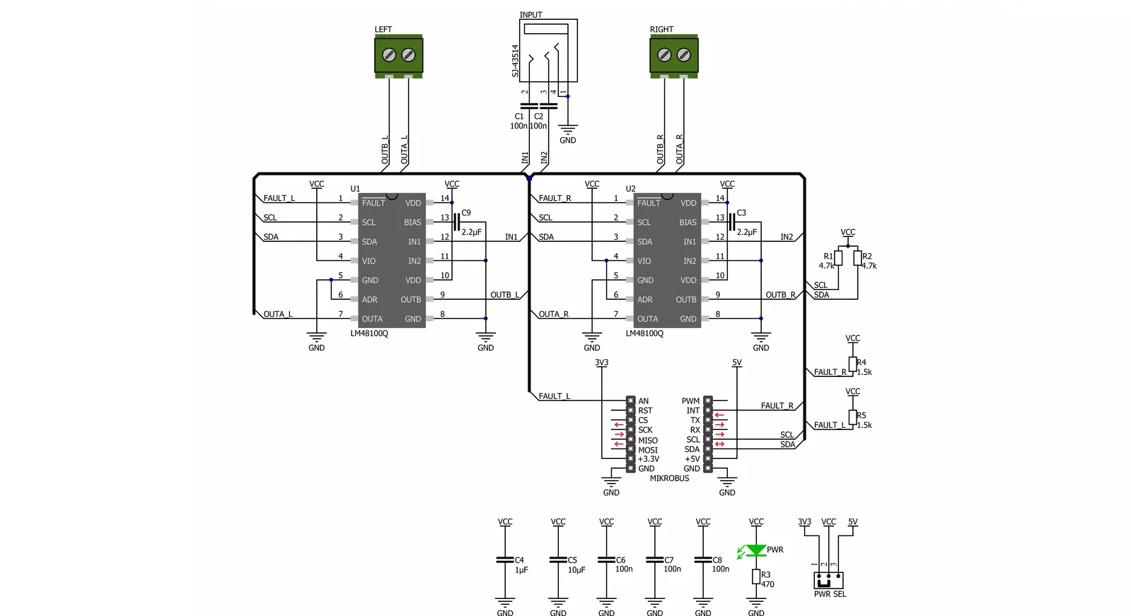
StereoAmp Click is based on two LM48100Qs, Boomer mono audio power amplifiers with output fault detection and volume control from Texas Instruments. The inputs of the amplifiers can be mixed/multiplexed to the device’s outputs. Each input has its own independent 32-step volume control. Each amplifier has short circuit and thermal protection, advanced click-and-pop suppression, and high PSRR. The StereoAmp Click features a 3.5mm audio jack as input and two pairs of screw terminals as output for connecting passive speakers. Each amplifier is used for one channel, left or right. The amplifiers are designed to drive a load differentially, a configuration better known as a bridge-tied load (BTL). BTL is an output configuration where the speakers are
connected (bridged) between two audio amplifier outputs. In a single-ended configuration, one side of the load is connected to the ground. Here both channels are connected, but one has an inverted signal. Compared to a single-ended configuration, BTL has two times more voltage swing across the load (speakers). The doubled voltage swing means four times more power to the speakers. This is ideal for applications and devices with lower supply voltage due to battery size. The output fault detection system can sense load conditions, protect the device during short circuit events, and detect open circuit conditions. The LM48100Q-Q1 output fault diagnostics are controlled through the I2C interface. In addition, the IC has an I2C selectable low-power shutdown mode that turns
off the device, reducing current consumption to 0.01μA. The StereoAmp Click uses the standard write-only 2-Wire I2C interface to communicate with the host MCU, supporting clock rates up to 400KHz. There are two fault detection pins, labeled FLL and FLR, according to a left or right channel. Those pins will go logic LOW if the fault condition occurs. This Click board™ can operate with either 3.3V or 5V logic voltage levels selected via the PWR SEL jumper. This way, both 3.3V and 5V capable MCUs can use the communication lines properly. However, the Click board™ comes equipped with a library containing easy-to-use functions and an example code that can be used, as a reference, for further development.

Features overview
Development board
Flip&Click PIC32MZ is a compact development board designed as a complete solution that brings the flexibility of add-on Click boards™ to your favorite microcontroller, making it a perfect starter kit for implementing your ideas. It comes with an onboard 32-bit PIC32MZ microcontroller, the PIC32MZ2048EFH100 from Microchip, four mikroBUS™ sockets for Click board™ connectivity, two USB connectors, LED indicators, buttons, debugger/programmer connectors, and two headers compatible with Arduino-UNO pinout. Thanks to innovative manufacturing technology,
it allows you to build gadgets with unique functionalities and features quickly. Each part of the Flip&Click PIC32MZ development kit contains the components necessary for the most efficient operation of the same board. In addition, there is the possibility of choosing the Flip&Click PIC32MZ programming method, using the chipKIT bootloader (Arduino-style development environment) or our USB HID bootloader using mikroC, mikroBasic, and mikroPascal for PIC32. This kit includes a clean and regulated power supply block through the USB Type-C (USB-C) connector. All communication
methods that mikroBUS™ itself supports are on this board, including the well-established mikroBUS™ socket, user-configurable buttons, and LED indicators. Flip&Click PIC32MZ development kit allows you to create a new application in minutes. Natively supported by Mikroe software tools, it covers many aspects of prototyping thanks to a considerable number of different Click boards™ (over a thousand boards), the number of which is growing every day.

Microcontroller Overview
MCU Card / MCU

Architecture
PIC32
MCU Memory (KB)
2048
Silicon Vendor
Microchip
Pin count
100
RAM (Bytes)
524288
Used MCU Pins
mikroBUS™ mapper
Take a closer look
Click board™ Schematic
Step by step
Project assembly

Start by selecting your development board and Click board™. Begin with the Flip&Click PIC32MZ as your development board.


Software Support
Library Description
This library contains API for StereoAmp Click driver.
Key functions:
stereoamp_set_power_on- This function set the power On of both channels by write to the Mode Control register address of LM48100Q-Q1 chip on StereoAmp Clickstereoamp_set_volume- This function set the volume of both channels to the Volume Control register address of LM48100Q-Q1 chip on StereoAmp Click
Open Source
Code example
The complete application code and a ready-to-use project are available through the NECTO Studio Package Manager for direct installation in the NECTO Studio. The application code can also be found on the MIKROE GitHub account.
/*!
 * \file
 * \brief StereoAmp Click example
 *
 * # Description
 * This is an example which demonstrates the use of StereoAmp Click board -
 * stereo amplifier and is ideal for battery operated devices or as a lab amplifier.
 *
 * The demo application is composed of two sections :
 *
 * ## Application Init
 * Application Init performs Logger and Click initialization.
 *
 * ## Application Task
 * This examples first set volume level 20 of 31 ( gain: 1,5 dB ) for 10 seconds.
 * After that, we increase the volume to level 10 ( gain: -13,5 dB ) for the next 10 seconds.
 * Results are being sent to the UART Terminal where you can track their changes.
 *
 * \author Mihajlo Djordjevic
 *
 */
// ------------------------------------------------------------------- INCLUDES

#include "board.h"
#include "log.h"
#include "stereoamp.h"

// ------------------------------------------------------------------ VARIABLES

static stereoamp_t stereoamp;
static log_t logger;

// ------------------------------------------------------ APPLICATION FUNCTIONS

void application_init ( void )
{
    log_cfg_t log_cfg;
    stereoamp_cfg_t cfg;

    /**
     * Logger initialization.
     * Default baud rate: 115200
     * Default log level: LOG_LEVEL_DEBUG
     * @note If USB_UART_RX and USB_UART_TX
     * are defined as HAL_PIN_NC, you will
     * need to define them manually for log to work.
     * See @b LOG_MAP_USB_UART macro definition for detailed explanation.
     */
    LOG_MAP_USB_UART( log_cfg );
    log_init( &logger, &log_cfg );
    log_info( &logger, "---- Application Init ----" );
    Delay_ms ( 500 );

    //  Click initialization.

    stereoamp_cfg_setup( &cfg );
    STEREOAMP_MAP_MIKROBUS( cfg, MIKROBUS_1 );
    stereoamp_init( &stereoamp, &cfg );

    log_printf( &logger, "--------------------------\r\n" );
    log_printf( &logger, " ---  StereoAmp Click --- \r\n" );
    log_printf( &logger, "--------------------------\r\n" );
    Delay_ms ( 1000 );

    stereoamp_default_cfg( &stereoamp );
    Delay_ms ( 1000 );

    log_printf( &logger, "         Power  On        \r\n" );
    stereoamp_set_power_on( &stereoamp );
    Delay_ms ( 500 );
    log_printf( &logger, "--------------------------\r\n" );

    log_printf( &logger, "     Set Volume: -80dB    \r\n" );
    stereoamp_set_volume( &stereoamp, STEREOAMP_GAIN_NEG_80dB );
    Delay_ms ( 500 );
    log_printf( &logger, "--------------------------\r\n" );

    log_printf( &logger, "       Enable Fault       \r\n" );
    stereoamp_enable_fault( &stereoamp );
    Delay_ms ( 500 );
    log_printf( &logger, "--------------------------\r\n" );

    log_printf( &logger, "     Enable Diagnostic    \r\n" );
    stereoamp_enable_diagnostic( &stereoamp );
    Delay_ms ( 500 );
    log_printf( &logger, "--------------------------\r\n" );

    log_printf( &logger, " -- Initialization done --\r\n" );
    log_printf( &logger, "--------------------------\r\n" );
    Delay_ms ( 500 );

    log_printf( &logger, "--------------------------\r\n" );
    log_printf( &logger, " -----  Play  Music ----- \r\n" );
    log_printf( &logger, "--------------------------\r\n" );
    Delay_ms ( 500 );
}

void application_task ( void )
{
    log_printf( &logger, "        Gain 1.5 dB        \r\n" );
    stereoamp_set_volume( &stereoamp, STEREOAMP_GAIN_1_5dB );
    // 10 seconds delay
    Delay_ms ( 1000 );
    Delay_ms ( 1000 );
    Delay_ms ( 1000 );
    Delay_ms ( 1000 );
    Delay_ms ( 1000 );
    Delay_ms ( 1000 );
    Delay_ms ( 1000 );
    Delay_ms ( 1000 );
    Delay_ms ( 1000 );
    Delay_ms ( 1000 );
    log_printf( &logger, "--------------------------\r\n" );

    log_printf( &logger, "        Gain -13.5 dB      \r\n" );
    stereoamp_set_volume( &stereoamp, STEREOAMP_GAIN_NEG_13_5dB );
    // 10 seconds delay
    Delay_ms ( 1000 );
    Delay_ms ( 1000 );
    Delay_ms ( 1000 );
    Delay_ms ( 1000 );
    Delay_ms ( 1000 );
    Delay_ms ( 1000 );
    Delay_ms ( 1000 );
    Delay_ms ( 1000 );
    Delay_ms ( 1000 );
    Delay_ms ( 1000 );
    log_printf( &logger, "--------------------------\r\n" );
}

int main ( void )
{
    /* Do not remove this line or clock might not be set correctly. */
    #ifdef PREINIT_SUPPORTED
    preinit();
    #endif

    application_init( );

    for ( ; ; )
    {
        application_task( );
    }

    return 0;
}

// ------------------------------------------------------------------------ END
Additional Support
Resources
Category:Amplifier


