Add small, blue, readable displays to various electronic projects with JSS-3011BUB-21, TLC5947 and PIC18F45K40
Useful for things like digital clocks, scoreboards, or any device where you need to show information clearly
Published Feb 21, 2024
Click board™
UT-S 7-SEG B 2 Click
Dev. board
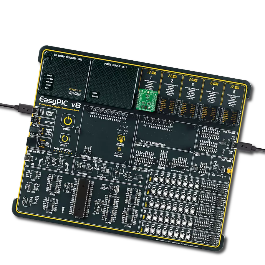
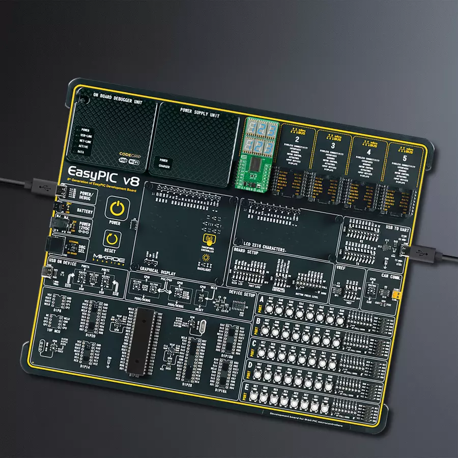
EasyPIC v8
Compiler
NECTO Studio
MCU
PIC18F45K40
Six ultra-thin displays capable of showing numbers, letters, and symbols in blue, making the information easy to read
A
A
Hardware Overview
How does it work?
UT-S 7-SEG B 2 Click is based on the TLC5947, a constant-current sink LED driver from Texas Instruments, alongside six ultra-thin blue single-digit numeric displays, the JSS-3011BUB-21. This high-intensity and reliable blue source color device is made with Indium-Gallium-Nitride light-emitting diode conducting material. It features low current operation, high light output, excellent character appearance, and is mechanically rugged. The display can work on 5V and 3.3V and has a common anode as its internal design. It consists
of seven blue LED segments that form an 8 number and the eighth segment as a decimal point, or DP. The communication between the host MCU and the UT-S 7-SEG B 2 Click is established via two TLC5947s, 24-channel 12-bit constant-current sink LED drivers from Analog Devices. This driver has a 4-wire serial interface using four inputs and a data output. The output-enable input (BLK) gates to all 24 outputs ON and OFF and is fast enough to be used as a PWM input for LED intensity control. The constant-current outputs are programmed together
to around 12mA using a single external resistor. This Click board™ can operate with either 3.3V or 5V logic voltage levels selected via the VCC SEL jumper. This way, both 3.3V and 5V capable MCUs can use the communication lines properly. Also, this Click board™ comes equipped with a library containing easy-to-use functions and an example code that can be used as a reference for further development.

Features overview
Development board
EasyPIC v8 is a development board specially designed for the needs of rapid development of embedded applications. It supports many high pin count 8-bit PIC microcontrollers from Microchip, regardless of their number of pins, and a broad set of unique functions, such as the first-ever embedded debugger/programmer. The development board is well organized and designed so that the end-user has all the necessary elements, such as switches, buttons, indicators, connectors, and others, in one place. Thanks to innovative manufacturing technology, EasyPIC v8 provides a fluid and immersive working experience, allowing access anywhere and under any
circumstances at any time. Each part of the EasyPIC v8 development board contains the components necessary for the most efficient operation of the same board. In addition to the advanced integrated CODEGRIP programmer/debugger module, which offers many valuable programming/debugging options and seamless integration with the Mikroe software environment, the board also includes a clean and regulated power supply module for the development board. It can use a wide range of external power sources, including a battery, an external 12V power supply, and a power source via the USB Type-C (USB-C) connector.
Communication options such as USB-UART, USB DEVICE, and CAN are also included, including the well-established mikroBUS™ standard, two display options (graphical and character-based LCD), and several different DIP sockets. These sockets cover a wide range of 8-bit PIC MCUs, from the smallest PIC MCU devices with only eight up to forty pins. EasyPIC v8 is an integral part of the Mikroe ecosystem for rapid development. Natively supported by Mikroe software tools, it covers many aspects of prototyping and development thanks to a considerable number of different Click boards™ (over a thousand boards), the number of which is growing every day.

Microcontroller Overview
MCU Card / MCU
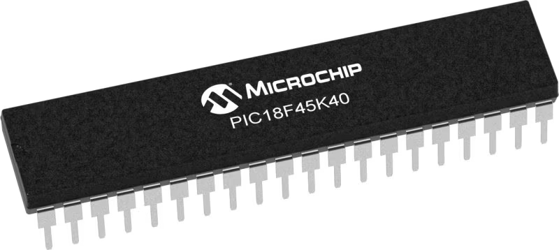
Architecture
PIC
MCU Memory (KB)
32
Silicon Vendor
Microchip
Pin count
40
RAM (Bytes)
2048
Used MCU Pins
mikroBUS™ mapper
Take a closer look
Click board™ Schematic

Step by step
Project assembly

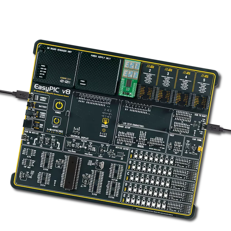
Start by selecting your development board and Click board™. Begin with the EasyPIC v8 as your development board.


Track your results in real time
Application Output
1. Application Output - In Debug mode, the 'Application Output' window enables real-time data monitoring, offering direct insight into execution results. Ensure proper data display by configuring the environment correctly using the provided tutorial.

2. UART Terminal - Use the UART Terminal to monitor data transmission via a USB to UART converter, allowing direct communication between the Click board™ and your development system. Configure the baud rate and other serial settings according to your project's requirements to ensure proper functionality. For step-by-step setup instructions, refer to the provided tutorial.

3. Plot Output - The Plot feature offers a powerful way to visualize real-time sensor data, enabling trend analysis, debugging, and comparison of multiple data points. To set it up correctly, follow the provided tutorial, which includes a step-by-step example of using the Plot feature to display Click board™ readings. To use the Plot feature in your code, use the function: plot(*insert_graph_name*, variable_name);. This is a general format, and it is up to the user to replace 'insert_graph_name' with the actual graph name and 'variable_name' with the parameter to be displayed.

Software Support
Library Description
This library contains API for UT-S 7-SEG B 2 Click driver.
Key functions:
uts7segb2_display_number- This function displays the desired number and brightness on the selected segmentsuts7segb2_display_character- This function displays the desired characters and brightness on the selected segmentsuts7segb2_set_led_output- This function sets the LED driver output
Open Source
Code example
The complete application code and a ready-to-use project are available through the NECTO Studio Package Manager for direct installation in the NECTO Studio. The application code can also be found on the MIKROE GitHub account.
/*!
 * @file main.c
 * @brief UT-S 7-SEG B 2 Click example
 *
 * # Description
 * This example demonstrates the use of the UT-S 7-SEG B 2 Click board
 * by writing and displaying the desired numbers on the screen.
 *
 * The demo application is composed of two sections :
 *
 * ## Application Init
 * Initialization of SPI module and log UART.
 * After driver initialization, the app executes a default configuration.
 *
 * ## Application Task
 * The demo application draws numbers, in hexadecimal format,
 * from 0h to FFFh on the top segment group and from FFFh to 0h on the bottom segment group.
 * Results are being sent to the UART Terminal, where you can track their changes.
 *
 * @author Mikroe Team
 *
 */

#include "board.h"
#include "log.h"
#include "uts7segb2.h"

static uts7segb2_t uts7segb2;
static log_t logger;
static uts7segb2_number_cfg_t number;

void application_init ( void )
{
    log_cfg_t log_cfg;  /**< Logger config object. */
    uts7segb2_cfg_t uts7segb2_cfg;  /**< Click config object. */

    /**
     * Logger initialization.
     * Default baud rate: 115200
     * Default log level: LOG_LEVEL_DEBUG
     * @note If USB_UART_RX and USB_UART_TX
     * are defined as HAL_PIN_NC, you will
     * need to define them manually for log to work.
     * See @b LOG_MAP_USB_UART macro definition for detailed explanation.
     */
    LOG_MAP_USB_UART( log_cfg );
    log_init( &logger, &log_cfg );
    log_info( &logger, " Application Init " );

    // Click initialization.
    uts7segb2_cfg_setup( &uts7segb2_cfg );
    UTS7SEGB2_MAP_MIKROBUS( uts7segb2_cfg, MIKROBUS_1 );
    if ( SPI_MASTER_ERROR == uts7segb2_init( &uts7segb2, &uts7segb2_cfg ) )
    {
        log_error( &logger, " Communication init." );
        for ( ; ; );
    }

    if ( UTS7SEGB2_ERROR == uts7segb2_default_cfg ( &uts7segb2 ) )
    {
        log_error( &logger, " Default configuration." );
        for ( ; ; );
    }

    number.brightness_top = UTS7SEGB2_BRIGHTNESS_DEFAULT;
    number.brightness_bottom = UTS7SEGB2_BRIGHTNESS_DEFAULT;
    number.base = UTS7SEGB2_BASE_NUM_SYS_HEXADECIMAL;
    number.dot_bit_mask = UTS7SEGB2_TOP_SEG_NO_DOT | UTS7SEGB2_BOTTOM_SEG_NO_DOT;
    log_info( &logger, " Application Task " );
    Delay_ms ( 100 );
}

void application_task ( void )
{
    for ( uint16_t num_cnt = 0; num_cnt <= UTS7SEGB2_HEXADECIMAL_NUM_MAX; num_cnt++ )
    {
        number.num_top = num_cnt;
        number.num_bottom = UTS7SEGB2_HEXADECIMAL_NUM_MAX - num_cnt;
        if ( UTS7SEGB2_OK == uts7segb2_display_number( &uts7segb2, number ) )
        {
            log_printf( &logger, " %.3X\r\n", number.num_top );
            log_printf( &logger, " %.3X\r\n\n", number.num_bottom );
            Delay_ms ( 100 );
        }
    }
    log_printf( &logger, " --------------\r\n\n" );
    Delay_ms ( 1000 );
}

int main ( void )
{
    /* Do not remove this line or clock might not be set correctly. */
    #ifdef PREINIT_SUPPORTED
    preinit();
    #endif

    application_init( );

    for ( ; ; )
    {
        application_task( );
    }

    return 0;
}

// ------------------------------------------------------------------------ END