Power your devices with finesse using L6986H and PIC18LF45K22
Synchronous step-down marvel!
Published Aug 01, 2023
Click board™
Step Down 2 Click
Dev. board
EasyPIC v8
Compiler
NECTO Studio
MCU
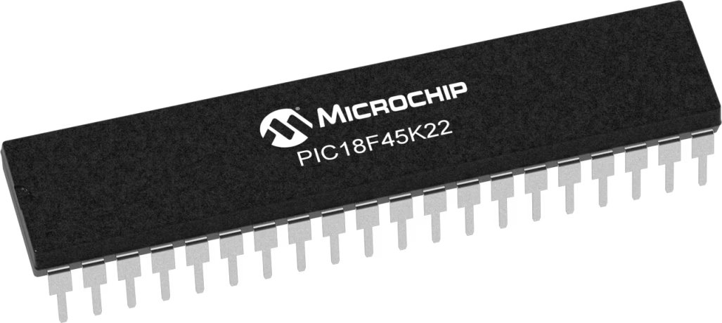
PIC18LF45K22
This step-down converter proves invaluable in high-efficiency applications, as it minimizes energy dissipation and maximizes device runtime
A
A
Hardware Overview
How does it work?
Step Down 2 Click is based on L6986HTR, a step-down monolithic switching regulator that delivers up to 2 A DC from STMicroelectronics. The output voltage adjustability ranges from 0.85 V to VIN. The "low consumption mode" (LCM) is designed for applications active during idle mode, so it maximizes the efficiency at light-load with controlled output voltage ripple. The "low noise mode" (LNM) makes the switching frequency constant and minimizes the output voltage ripple overload current range, meeting the low noise application specifications. The output voltage supervisor manages the reset phase for any digital load (µC, FPGA). The RST open collector output can also run voltage sequencing during the power-up phase. The synchronous rectification, designed for high efficiency at medium - heavy load, and the high switching frequency capability make the size of the application compact. Pulse-by-pulse current sensing on both power elements
implements effective constant current protection. The L6986H device is based on a "peak current mode" and constant frequency control. Consequently, the intersection between the error amplifier output and the sensed inductor current generates the PWM control signal to drive the power switch. The device features LNM (low noise mode), which implements a forced PWM operation over different loading conditions. The LNM features a constant switching frequency to minimize the noise in the final application and a constant voltage ripple at fixed VIN. The regulator in steady loading conditions never skips pulses, and it operates in continuous conduction mode (CCM) over the different loading conditions, thus making this operation mode ideal for noise-sensitive applications. The overvoltage protection monitors the VOUT pin and enables the low-side MOSFET to discharge the output capacitor if the output voltage is 20% over the nominal value.
This is second-level protection and should never be triggered in normal operating conditions if the system is properly dimensioned. In other words, the selection of the external power components and the dynamic performance determined by the compensation network should guarantee an output voltage regulation within the overvoltage threshold, even during the worst-case scenario regarding load transitions. The protection is reliable and can operate even during normal load transitions for a system whose dynamic performance is not in line with the load dynamic request. As a consequence, the output voltage regulation would be affected. Because of its features' main possibilities, the Step Down 2 Click is ideally used for programmable logic controllers (PLCs), decentralized intelligent nodes, sensors, and low noise applications (LNM).

Features overview
Development board
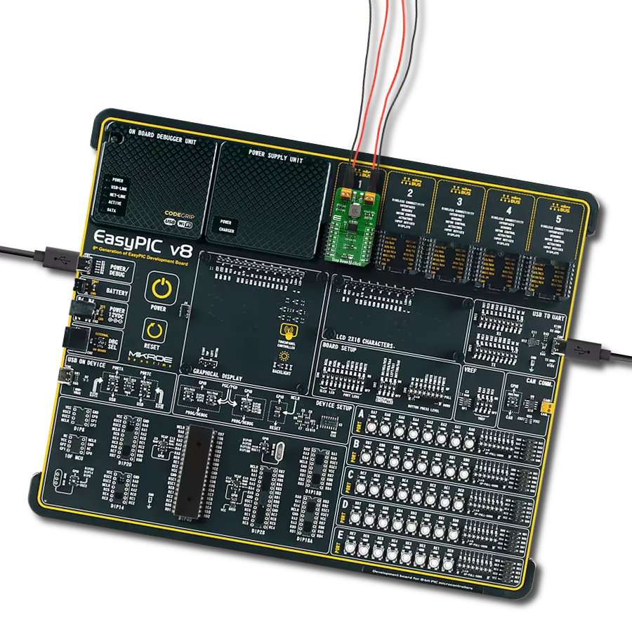
EasyPIC v8 is a development board specially designed for the needs of rapid development of embedded applications. It supports many high pin count 8-bit PIC microcontrollers from Microchip, regardless of their number of pins, and a broad set of unique functions, such as the first-ever embedded debugger/programmer. The development board is well organized and designed so that the end-user has all the necessary elements, such as switches, buttons, indicators, connectors, and others, in one place. Thanks to innovative manufacturing technology, EasyPIC v8 provides a fluid and immersive working experience, allowing access anywhere and under any
circumstances at any time. Each part of the EasyPIC v8 development board contains the components necessary for the most efficient operation of the same board. In addition to the advanced integrated CODEGRIP programmer/debugger module, which offers many valuable programming/debugging options and seamless integration with the Mikroe software environment, the board also includes a clean and regulated power supply module for the development board. It can use a wide range of external power sources, including a battery, an external 12V power supply, and a power source via the USB Type-C (USB-C) connector.
Communication options such as USB-UART, USB DEVICE, and CAN are also included, including the well-established mikroBUS™ standard, two display options (graphical and character-based LCD), and several different DIP sockets. These sockets cover a wide range of 8-bit PIC MCUs, from the smallest PIC MCU devices with only eight up to forty pins. EasyPIC v8 is an integral part of the Mikroe ecosystem for rapid development. Natively supported by Mikroe software tools, it covers many aspects of prototyping and development thanks to a considerable number of different Click boards™ (over a thousand boards), the number of which is growing every day.

Microcontroller Overview
MCU Card / MCU
Architecture
PIC
MCU Memory (KB)
32
Silicon Vendor
Microchip
Pin count
40
RAM (Bytes)
1536
Used MCU Pins
mikroBUS™ mapper
Take a closer look
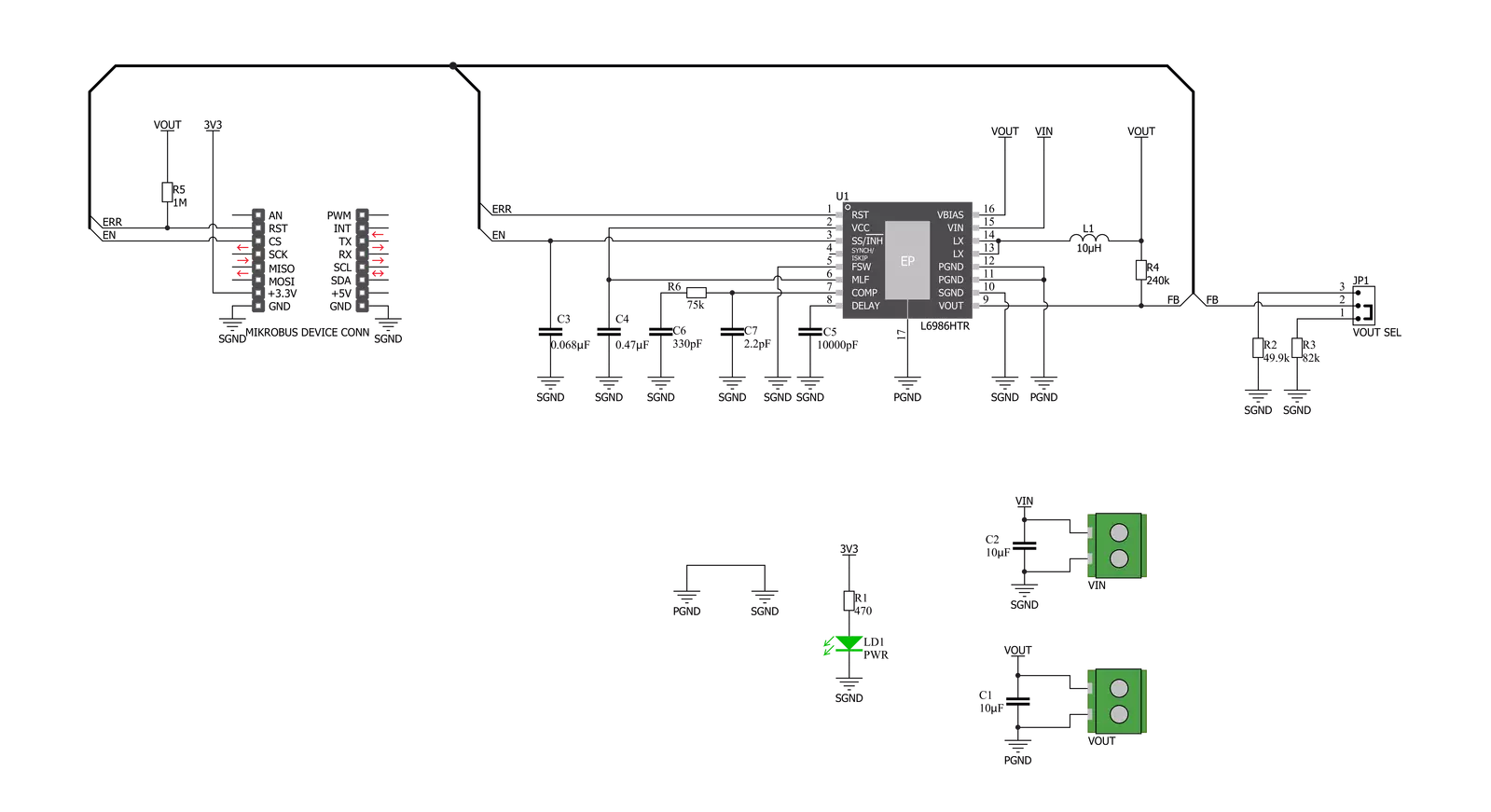
Click board™ Schematic
Step by step
Project assembly

Start by selecting your development board and Click board™. Begin with the EasyPIC v8 as your development board.


Software Support
Library Description
This library contains API for Step Down 2 Click driver.
Key functions:
stepdown2_digital_read_rst- This function reads the digital signal from the RST pinstepdown2_digital_write_cs- This function writes the specified digital signal to the CS pin
Open Source
Code example
The complete application code and a ready-to-use project are available through the NECTO Studio Package Manager for direct installation in the NECTO Studio. The application code can also be found on the MIKROE GitHub account.
/*!
 * \file
 * \brief Step Down 2 Click example
 *
 * # Description
 * This example showcases how to initialize and use the Step Down 2 Click. The Click is a
 * step-down monolithic switching regulator able to deliver up to 2 A (DC).
 *
 * The demo application is composed of two sections :
 *
 * ## Application Init
 * This function initializes and configures the logger and Click modules.
 *
 * ## Application Task
 * This function checks error input on the RST pin and reports if the device is working properly
 * or not. It does so every second.
 *
 * \author MikroE Team
 *
 */
// ------------------------------------------------------------------- INCLUDES

#include "board.h"
#include "log.h"
#include "stepdown2.h"

// ------------------------------------------------------------------ VARIABLES

static stepdown2_t stepdown2;
static log_t logger;

// ------------------------------------------------------ APPLICATION FUNCTIONS

void application_init ( )
{
    log_cfg_t log_cfg;
    stepdown2_cfg_t cfg;

    /**
     * Logger initialization.
     * Default baud rate: 115200
     * Default log level: LOG_LEVEL_DEBUG
     * @note If USB_UART_RX and USB_UART_TX
     * are defined as HAL_PIN_NC, you will
     * need to define them manually for log to work.
     * See @b LOG_MAP_USB_UART macro definition for detailed explanation.
     */
    LOG_MAP_USB_UART( log_cfg );
    log_init( &logger, &log_cfg );
    log_info(&logger, "---- Application Init ----");

    //  Click initialization.

    stepdown2_cfg_setup( &cfg );
    STEPDOWN2_MAP_MIKROBUS( cfg, MIKROBUS_1 );
    stepdown2_init( &stepdown2, &cfg );

    stepdown2_digital_write_cs( &stepdown2, 1 );
    Delay_100ms( );
}

void application_task ( )
{
    if ( stepdown2_digital_read_rst( &stepdown2 ) )
    {
        log_printf( &logger, " * The device works as it should. *\r\n" );
    }
    else
    {
        log_printf( &logger, " * The device does not work as it should. *\r\n" );
    }

    Delay_1sec( );
}

int main ( void )
{
    /* Do not remove this line or clock might not be set correctly. */
    #ifdef PREINIT_SUPPORTED
    preinit();
    #endif

    application_init( );

    for ( ; ; )
    {
        application_task( );
    }

    return 0;
}

// ------------------------------------------------------------------------ END


