Unlock precision with our programmable gain amplifier based on LTC6912 and PIC18LF47K42
Scale up your signals

Published Jul 28, 2023
Click board™
GainAMP Click
Dev. board
EasyPIC v8
Compiler
NECTO Studio
MCU
PIC18LF47K42
Our PGA solution enables seamless signal amplification with customizable gain settings, making it the ideal choice for your applications where precision and flexibility are paramount
A
A
Hardware Overview
How does it work?
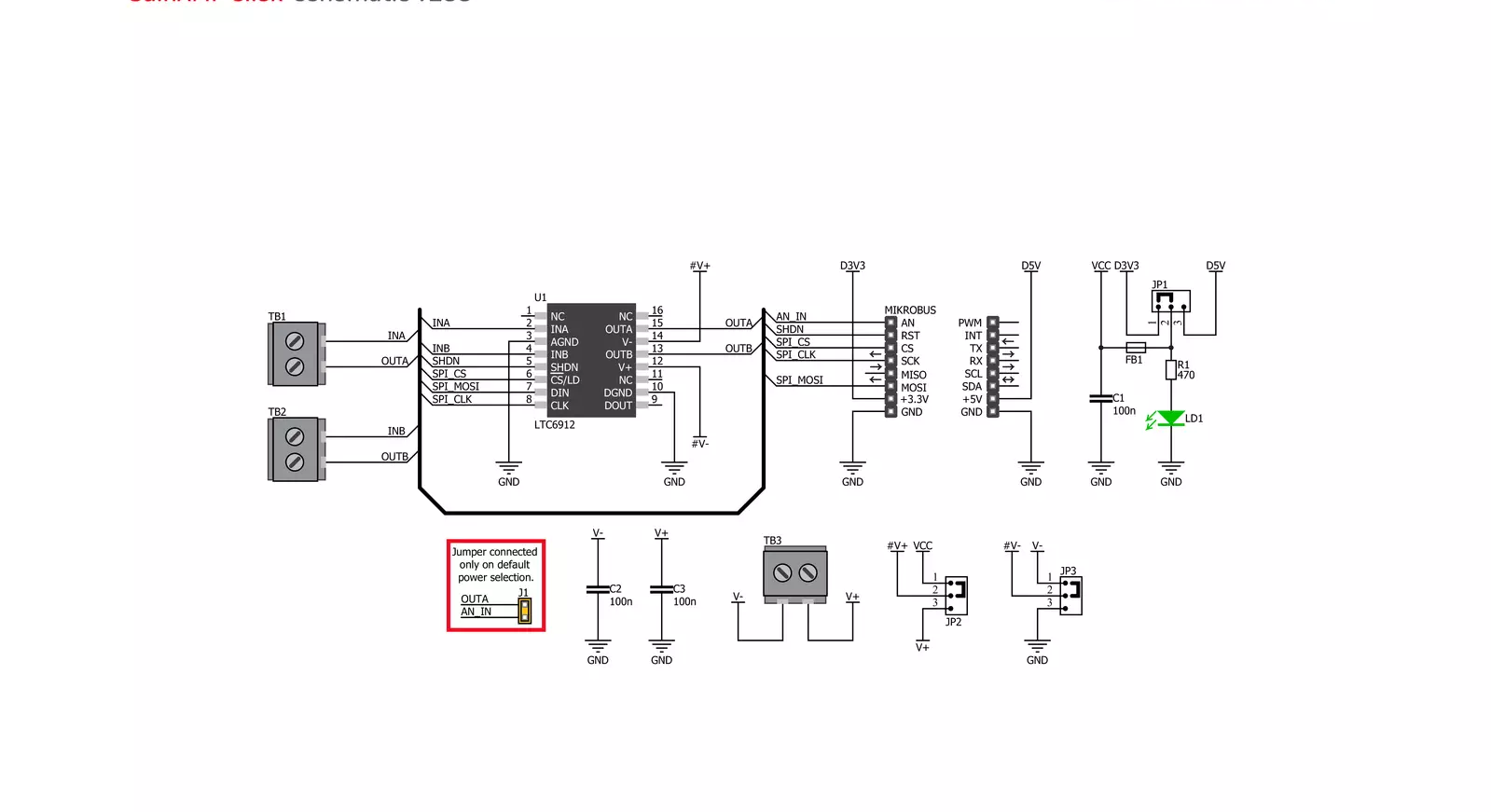
GainAMP Click is based on the LTC6912, a dual channel, low noise, digitally programmable gain amplifier (PGA) from Analog Devices. The click is designed to work on either a 3.3V or 5V power supply. It communicates with the target MCU over the SPI interface, with additional functionality provided by the following pins on the mikroBUS™ line: AN, RST. GainAMP Click also features three
screw terminals and a power indication LED. The gains for both channels are independently programmable, using a 3-wire SPI interface to select voltage gains of 0, 1, 2, 5, 10, 20, 50, and 100V/V (LTC6912-1). All gains are inverting. The LTC6912 consists of 2 matched amplifiers with rail-to-rail outputs. When operated with unity gain, they will also process rail-to-rail input signals.
A half-supply reference generated internally at the AGND pin supports single power supply applications. It operates from single or split supplies from 2.7V to 10.5V in total. A programmable-gain amplifier (PGA) is an electronic amplifier whose gain can be controlled externally (by analog or digital signals).

Features overview
Development board
EasyPIC v8 is a development board specially designed for the needs of rapid development of embedded applications. It supports many high pin count 8-bit PIC microcontrollers from Microchip, regardless of their number of pins, and a broad set of unique functions, such as the first-ever embedded debugger/programmer. The development board is well organized and designed so that the end-user has all the necessary elements, such as switches, buttons, indicators, connectors, and others, in one place. Thanks to innovative manufacturing technology, EasyPIC v8 provides a fluid and immersive working experience, allowing access anywhere and under any
circumstances at any time. Each part of the EasyPIC v8 development board contains the components necessary for the most efficient operation of the same board. In addition to the advanced integrated CODEGRIP programmer/debugger module, which offers many valuable programming/debugging options and seamless integration with the Mikroe software environment, the board also includes a clean and regulated power supply module for the development board. It can use a wide range of external power sources, including a battery, an external 12V power supply, and a power source via the USB Type-C (USB-C) connector.
Communication options such as USB-UART, USB DEVICE, and CAN are also included, including the well-established mikroBUS™ standard, two display options (graphical and character-based LCD), and several different DIP sockets. These sockets cover a wide range of 8-bit PIC MCUs, from the smallest PIC MCU devices with only eight up to forty pins. EasyPIC v8 is an integral part of the Mikroe ecosystem for rapid development. Natively supported by Mikroe software tools, it covers many aspects of prototyping and development thanks to a considerable number of different Click boards™ (over a thousand boards), the number of which is growing every day.

Microcontroller Overview
MCU Card / MCU
Architecture
PIC
MCU Memory (KB)
128
Silicon Vendor
Microchip
Pin count
40
RAM (Bytes)
8192
Used MCU Pins
mikroBUS™ mapper
Take a closer look
Click board™ Schematic
Step by step
Project assembly

Start by selecting your development board and Click board™. Begin with the EasyPIC v8 as your development board.


Track your results in real time
Application Output
1. Application Output - In Debug mode, the 'Application Output' window enables real-time data monitoring, offering direct insight into execution results. Ensure proper data display by configuring the environment correctly using the provided tutorial.

2. UART Terminal - Use the UART Terminal to monitor data transmission via a USB to UART converter, allowing direct communication between the Click board™ and your development system. Configure the baud rate and other serial settings according to your project's requirements to ensure proper functionality. For step-by-step setup instructions, refer to the provided tutorial.

3. Plot Output - The Plot feature offers a powerful way to visualize real-time sensor data, enabling trend analysis, debugging, and comparison of multiple data points. To set it up correctly, follow the provided tutorial, which includes a step-by-step example of using the Plot feature to display Click board™ readings. To use the Plot feature in your code, use the function: plot(*insert_graph_name*, variable_name);. This is a general format, and it is up to the user to replace 'insert_graph_name' with the actual graph name and 'variable_name' with the parameter to be displayed.

Software Support
Library Description
This library contains API for GainAMP Click driver.
Key functions:
gainamp_read_an_pin_value- GainAMP read AN pin value functiongainamp_read_an_pin_voltage- GainAMP read AN pin voltage level functiongainamp_set_gain- Function for sets gain of the GainAMP Click
Open Source
Code example
The complete application code and a ready-to-use project are available through the NECTO Studio Package Manager for direct installation in the NECTO Studio. The application code can also be found on the MIKROE GitHub account.
/*!
 * @file main.c
 * @brief GainAMP Click example
 *
 * # Description
 * This is an example that demonstrates the use of the GainAMP Click board.
 *
 * The demo application is composed of two sections :
 *
 * ## Application Init
 * Initializes SPI module and set CS pin and RST pin as OUTPUT,
 * initialization driver init and resets chip.
 *
 * ## Application Task
 * Sets the gain for both channels, channel A and channel B.
 *
 * @author Stefan Ilic
 *
 */

#include "board.h"
#include "log.h"
#include "gainamp.h"

static gainamp_t gainamp;
static log_t logger;

void application_init ( void )
{
    log_cfg_t log_cfg;  /**< Logger config object. */
    gainamp_cfg_t gainamp_cfg;  /**< Click config object. */

    /**
     * Logger initialization.
     * Default baud rate: 115200
     * Default log level: LOG_LEVEL_DEBUG
     * @note If USB_UART_RX and USB_UART_TX
     * are defined as HAL_PIN_NC, you will
     * need to define them manually for log to work.
     * See @b LOG_MAP_USB_UART macro definition for detailed explanation.
     */
    LOG_MAP_USB_UART( log_cfg );
    log_init( &logger, &log_cfg );
    log_info( &logger, " Application Init " );

    // Click initialization.

    gainamp_cfg_setup( &gainamp_cfg );
    GAINAMP_MAP_MIKROBUS( gainamp_cfg, MIKROBUS_1 );
    err_t init_flag  = gainamp_init( &gainamp, &gainamp_cfg );
    if ( ( SPI_MASTER_ERROR == init_flag ) || ( ADC_ERROR == init_flag ) ) {
        log_error( &logger, " Application Init Error. " );
        log_info( &logger, " Please, run program again... " );

        for ( ; ; );
    }
    gainamp_reset( &gainamp );
    Delay_ms( 100 );

    log_info( &logger, " Application Task " );
}

void application_task ( void )
{
    gainamp_set_gain( &gainamp, GAINAMP_CHANNEL_A_x1 | GAINAMP_CHANNEL_B_x5 );
    Delay_ms( 10000 );

    gainamp_set_gain( &gainamp, GAINAMP_CHANNEL_A_x10 | GAINAMP_CHANNEL_B_x100 );
    Delay_ms( 10000 );
}

void main ( void )
{
    application_init( );

    for ( ; ; ) {
        application_task( );
    }
}

// ------------------------------------------------------------------------ END


