Explore the potential of H-bridge gate driver with MC33883 and PIC18F46K40
Seamless switching, ultimate control
Published Jul 23, 2023
Click board™
H-Bridge Driver Click
Dev. board
EasyPIC v8
Compiler
NECTO Studio
MCU
PIC18F46K40
Unlock a new era of precision, innovation, and efficiency. Add an H-bridge gate driver with an integrated charge pump and independent high and low side gate driver channels to your design!
A
A
Hardware Overview
How does it work?
H-Bridge Driver Click is based on the MC33883, an H-bridge gate driver (or full-bridge pre-driver) with an integrated charge pump and independent high and low-side driver channels from NXP Semiconductors. Gate driver outputs can source and sink up to 1.0A peak current pulses, permitting large gate-charge MOSFETs to be driven or high pulse-width modulation (PWM) frequencies to be utilized. It also supports a Sleep mode of operation with its low supply current, typical of 10μA. The VIN1 and VIN2 terminals are the power supply inputs to the device. VIN1 is used for the output high-side drivers and the charge pump, while VIN2 is used for the linear regulation. They can be connected together or with different voltage
values, with VIN1 up to 45V and VIN2 up to 28V. These pins also have undervoltage (UV) and overvoltage (OV) shutdown features. If one of the supply voltages drops below the undervoltage threshold or rises above the overvoltage threshold, the gate outputs are switched low to switch off the external MOSFETs. When the supply returns to a level above the UV threshold or below the OV threshold, the device resumes normal operation according to the established condition of the input pins. Four separate pins independently control the gate driver channels, routed to the RST, AN, PWM, and INT pins of the mikroBUS™ socket. Those pins allow the device to be optionally configured as two independent high-side gate
drivers and two independent low-side gate drivers. In addition, it also has a pin used to place the device in Sleep mode. When the GEN pin, routed to the CS pin of the mikroBUS™ socket, is in a logic low state, the device is in Sleep mode; otherwise, it is fully operational. This Click board™ can operate with either 3.3V or 5V logic voltage levels selected via the VCC SEL jumper. This way, both 3.3V and 5V capable MCUs can use the communication lines properly. However, the Click board™ comes equipped with a library containing easy-to-use functions and an example code that can be used, as a reference, for further development.

Features overview
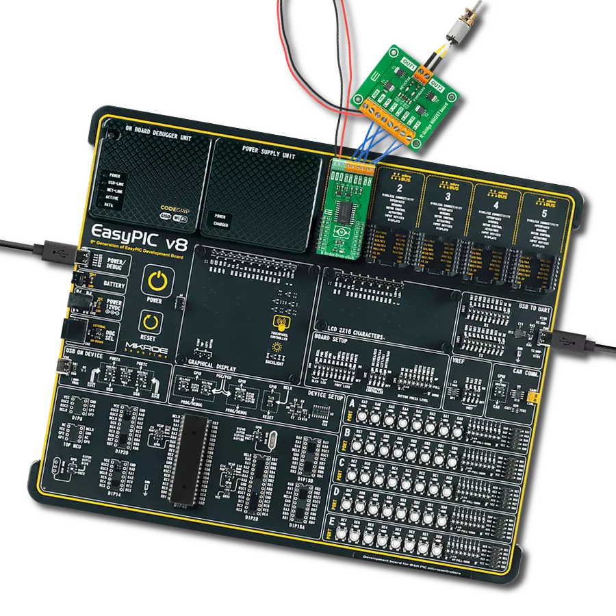
Development board
EasyPIC v8 is a development board specially designed for the needs of rapid development of embedded applications. It supports many high pin count 8-bit PIC microcontrollers from Microchip, regardless of their number of pins, and a broad set of unique functions, such as the first-ever embedded debugger/programmer. The development board is well organized and designed so that the end-user has all the necessary elements, such as switches, buttons, indicators, connectors, and others, in one place. Thanks to innovative manufacturing technology, EasyPIC v8 provides a fluid and immersive working experience, allowing access anywhere and under any
circumstances at any time. Each part of the EasyPIC v8 development board contains the components necessary for the most efficient operation of the same board. In addition to the advanced integrated CODEGRIP programmer/debugger module, which offers many valuable programming/debugging options and seamless integration with the Mikroe software environment, the board also includes a clean and regulated power supply module for the development board. It can use a wide range of external power sources, including a battery, an external 12V power supply, and a power source via the USB Type-C (USB-C) connector.
Communication options such as USB-UART, USB DEVICE, and CAN are also included, including the well-established mikroBUS™ standard, two display options (graphical and character-based LCD), and several different DIP sockets. These sockets cover a wide range of 8-bit PIC MCUs, from the smallest PIC MCU devices with only eight up to forty pins. EasyPIC v8 is an integral part of the Mikroe ecosystem for rapid development. Natively supported by Mikroe software tools, it covers many aspects of prototyping and development thanks to a considerable number of different Click boards™ (over a thousand boards), the number of which is growing every day.

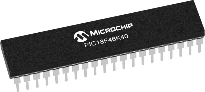
Microcontroller Overview
MCU Card / MCU
Architecture
PIC
MCU Memory (KB)
64
Silicon Vendor
Microchip
Pin count
40
RAM (Bytes)
3728
You complete me!
Accessories
H-Bridge MOSFET board represents an easy-to-use adapter board that allows the user to exercise all the functions of the H-Bridge Driver Click board™. This board has five 5.08mm pitch screw terminals to connect power and loads easily. Three of them on the left side of the board are suitable for a target H-Bridge Driver Click board™ connection with appropriate high and low side gate drive channels used to control the outputs or functions inside the circuit. The first VIN terminal on the upper-left board side represents the PSMN019-100YLX MOSFET’s power supply connector, allowing an operating voltage range like the connected H-Bridge Driver Click board™. On the right side of the board, the OUT terminal is used to drive a load, such as a brushed DC motor. This board also provides two LED indicators labeled REVERSE and FORWARD to indicate when output operates reverse or forward.

DC Gear Motor - 430RPM (3-6V) represents an all-in-one combination of a motor and gearbox, where the addition of gear leads to a reduction of motor speed while increasing the torque output. This gear motor has a spur gearbox, making it a highly reliable solution for applications with lower torque and speed requirements. The most critical parameters for gear motors are speed, torque, and efficiency, which are, in this case, 520RPM with no load and 430RPM at maximum efficiency, alongside a current of 60mA and a torque of 50g.cm. Rated for a 3-6V operational voltage range and clockwise/counterclockwise rotation direction, this motor represents an excellent solution for many functions initially performed by brushed DC motors in robotics, medical equipment, electric door locks, and much more.

Used MCU Pins
mikroBUS™ mapper
Take a closer look
Click board™ Schematic

Step by step
Project assembly

Start by selecting your development board and Click board™. Begin with the EasyPIC v8 as your development board.


Track your results in real time
Application Output
1. Application Output - In Debug mode, the 'Application Output' window enables real-time data monitoring, offering direct insight into execution results. Ensure proper data display by configuring the environment correctly using the provided tutorial.

2. UART Terminal - Use the UART Terminal to monitor data transmission via a USB to UART converter, allowing direct communication between the Click board™ and your development system. Configure the baud rate and other serial settings according to your project's requirements to ensure proper functionality. For step-by-step setup instructions, refer to the provided tutorial.

3. Plot Output - The Plot feature offers a powerful way to visualize real-time sensor data, enabling trend analysis, debugging, and comparison of multiple data points. To set it up correctly, follow the provided tutorial, which includes a step-by-step example of using the Plot feature to display Click board™ readings. To use the Plot feature in your code, use the function: plot(*insert_graph_name*, variable_name);. This is a general format, and it is up to the user to replace 'insert_graph_name' with the actual graph name and 'variable_name' with the parameter to be displayed.

Software Support
Library Description
This library contains API for H-Bridge Driver Click driver.
Key functions:
hbridgedriver_glo_enable- Global enable functionhbridgedriver_reverse- H-Bridge mode reverse functionhbridgedriver_forward- H-Bridge mode forward function
Open Source
Code example
The complete application code and a ready-to-use project are available through the NECTO Studio Package Manager for direct installation in the NECTO Studio. The application code can also be found on the MIKROE GitHub account.
/*!
 * @file main.c
 * @brief H-Bridge Driver Click Example.
 *
 * # Description
 * This is an example that demonstrates the use of the H-Bridge Driver Click board.
 *
 * The demo application is composed of two sections :
 *
 * ## Application Init
 * Initializes GPIO and LOG structures, and sets AN, RST, CS, PWM and
 * INT pins as output and start to write log.
 *
 * ## Application Task
 * Demonstrates use of the H-Bridge Driver Click board by turning connected MOSFETs
 * gates high or low in order to drive the motor forward, in reverse, brake or coast.
 *
 * @author Stefan Ilic
 *
 */

#include "board.h"
#include "log.h"
#include "hbridgedriver.h"

static hbridgedriver_t hbridgedriver;   /**< H-Bridge Driver Click driver object. */
static log_t logger;    /**< Logger object. */

void application_init ( void )
{
    log_cfg_t log_cfg;  /**< Logger config object. */
    hbridgedriver_cfg_t hbridgedriver_cfg;  /**< Click config object. */

    /**
     * Logger initialization.
     * Default baud rate: 115200
     * Default log level: LOG_LEVEL_DEBUG
     * @note If USB_UART_RX and USB_UART_TX
     * are defined as HAL_PIN_NC, you will
     * need to define them manually for log to work.
     * See @b LOG_MAP_USB_UART macro definition for detailed explanation.
     */
    LOG_MAP_USB_UART( log_cfg );
    log_init( &logger, &log_cfg );
    log_info( &logger, " Application Init " );

    // Click initialization.
    hbridgedriver_cfg_setup( &hbridgedriver_cfg );
    HBRIDGEDRIVER_MAP_MIKROBUS( hbridgedriver_cfg, MIKROBUS_1 );
    if ( DIGITAL_OUT_UNSUPPORTED_PIN == hbridgedriver_init( &hbridgedriver, &hbridgedriver_cfg ) )
    {
        log_error( &logger, " Communication init." );
        for ( ; ; );
    }
    hbridgedriver_glo_enable( &hbridgedriver, HBRIDGEDRIVER_PROP_EN );
    Delay_ms ( 100 );
    log_info( &logger, " Application Task " );
}

void application_task ( void )
{
    log_printf( &logger, " The motor turns forward! \r\n" );
    hbridgedriver_forward( &hbridgedriver );
    Delay_ms ( 1000 );
    Delay_ms ( 1000 );
    Delay_ms ( 1000 );
    log_printf( &logger, " The motor brakes! \r\n" );
    hbridgedriver_braking( &hbridgedriver );
    Delay_ms ( 1000 );
    Delay_ms ( 1000 );
    Delay_ms ( 1000 );
    log_printf( &logger, " The motor turns in reverse \r\n" );
    hbridgedriver_reverse( &hbridgedriver );
    Delay_ms ( 1000 );
    Delay_ms ( 1000 );
    Delay_ms ( 1000 );
    log_printf( &logger, " The motor coasting \r\n" );
    hbridgedriver_coasting( &hbridgedriver );
    Delay_ms ( 1000 );
    Delay_ms ( 1000 );
    Delay_ms ( 1000 );
}

int main ( void )
{
    /* Do not remove this line or clock might not be set correctly. */
    #ifdef PREINIT_SUPPORTED
    preinit();
    #endif

    application_init( );

    for ( ; ; )
    {
        application_task( );
    }

    return 0;
}

// ------------------------------------------------------------------------ END


