Discover the future of temperature measurement with MLX90632 and PIC18LF46K40
Touchless temperature insights

Published Nov 07, 2023
Click board™
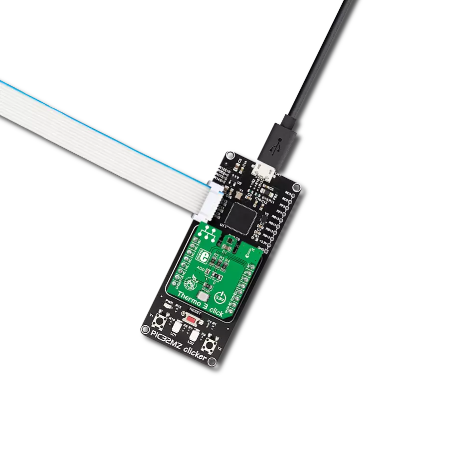
IrThermo 3 Click
Dev. board
EasyPIC v8
Compiler
NECTO Studio
MCU
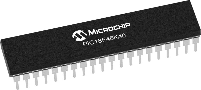
PIC18LF46K40
Ensure safety and accuracy in temperature monitoring with our contactless infrared solution, offering a reliable and efficient way to measure object temperatures.
A
A
Hardware Overview
How does it work?
IrThermo 3 Click is based on the MLX90632, a FIR sensor from Melexis as the contactless temperature sensor. This sensor is a thermopile IR sensor. A thermopile sensor is actually a serially connected thermocouple array, with hot junctions located on the heat absorbing membrane. The cold junctions are located on a cold base, providing the reference point for generating the voltage. Due to the low-temperature capacity of the membrane, it will react to the heat radiation, generating voltage via the thermoelectric effect. The ASSP circuitry of the MLX90632 sensor filters and amplifies the sensor signal, preventing interferences from external sources, such as localized thermal variations (air turbulence, or thermal differences across the sensor itself) to affect the measurement, yielding the highest accuracy of up to ±1℃. However, excessive disturbances and variations will affect the accuracy. The device is driven by a state machine, which controls the operation of several internal sections: thermal sensors, programmable gain amplifier, ADC converter, digital filtering, memory, and communication sections. The MLX90632 FIR sensor is factory calibrated in wide temperature range: -20°C to 80°C for ambient (sensor) temperature and --20°C to 200°C for the object temperature. An integrated thermal sensor allows
ambient temperature measurement independently of the thermopile itself, allowing accurate calibration calculations to be performed. EEPROM area with 256 locations of 16-bit words contains the calibration constants and trimming values. Along with the measurement from the integrated ambient temperature sensor (which measures the temperature of the sensor itself), the EEPROM information is used in the calculations. Formulas for the calculations can be found in the MLX90632 datasheet, and the host MCU should contain a firmware which processes the raw data from the sensor, by applying the calculations. The measurement data is stored in RAM locations, which is 96 16-bit words long. The rest of the RAM can be used for storing temporary results or some other auxiliary data. The STATUS register offers information about the status: the device is busy, EEPROM busy, data is ready and so on. The CONTROL register sets operating modes and initiates measurement while in a SLEEP mode. The last register controls the I2C slave address LSB and these three registers are located in the REGISTERS memory area. The entire memory map with the detailed information about all the EEPROM and register locations is provided in the MLX90632 datasheet. There are three modes of operation and depending on the working
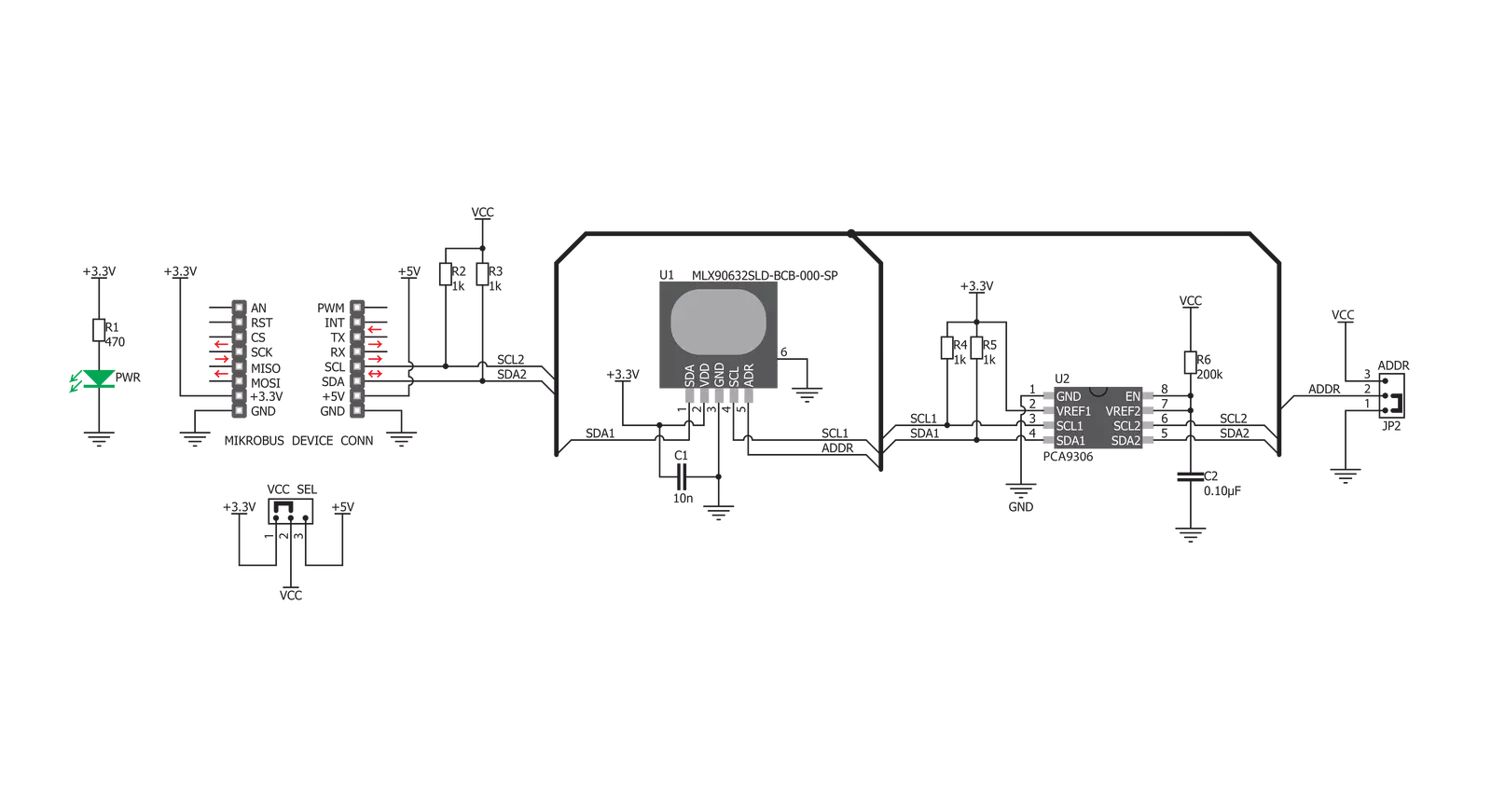
conditions, the appropriate mode can be selected in the CONTROL register: SLEEP mode - or SLEEPING STEP mode uses the least power of all modes. The device turns off unneeded sections until a command is received via the CONTROL register (SOC bit). Upon receiving the command, device powers on, performs a measurement and reverts back to the SLEEP mode. STEP mode uses more power as the device remains powered. The actual measurement is paused until a command is received (SOC bit of the CONTROL register). Upon receiving the command, the device performs a measurement and waits for the next command. CONTINUOUS mode performs measurements continuously. This mode consumes the most power, but the new data is constantly gathered, providing most accurate measurement with no lag. The device can be configured to have high refresh rates (down to 16ms). The default refresh rate is 0.5s. There are two SMD jumpers on this Click board™. One jumper is used to set the LSB of the I2C address of the device and it is labeled as the ADDR. The other SMD jumper is labeled as the VCC SEL and it is used to provide reference voltage for the PCA9306, a bi-directional I2C level shifter so that the Click board™ can be interfaced with both 3.3V and 5V MCUs.

Features overview
Development board
EasyPIC v8 is a development board specially designed for the needs of rapid development of embedded applications. It supports many high pin count 8-bit PIC microcontrollers from Microchip, regardless of their number of pins, and a broad set of unique functions, such as the first-ever embedded debugger/programmer. The development board is well organized and designed so that the end-user has all the necessary elements, such as switches, buttons, indicators, connectors, and others, in one place. Thanks to innovative manufacturing technology, EasyPIC v8 provides a fluid and immersive working experience, allowing access anywhere and under any
circumstances at any time. Each part of the EasyPIC v8 development board contains the components necessary for the most efficient operation of the same board. In addition to the advanced integrated CODEGRIP programmer/debugger module, which offers many valuable programming/debugging options and seamless integration with the Mikroe software environment, the board also includes a clean and regulated power supply module for the development board. It can use a wide range of external power sources, including a battery, an external 12V power supply, and a power source via the USB Type-C (USB-C) connector.
Communication options such as USB-UART, USB DEVICE, and CAN are also included, including the well-established mikroBUS™ standard, two display options (graphical and character-based LCD), and several different DIP sockets. These sockets cover a wide range of 8-bit PIC MCUs, from the smallest PIC MCU devices with only eight up to forty pins. EasyPIC v8 is an integral part of the Mikroe ecosystem for rapid development. Natively supported by Mikroe software tools, it covers many aspects of prototyping and development thanks to a considerable number of different Click boards™ (over a thousand boards), the number of which is growing every day.

Microcontroller Overview
MCU Card / MCU
Architecture
PIC
MCU Memory (KB)
64
Silicon Vendor
Microchip
Pin count
40
RAM (Bytes)
3728
Used MCU Pins
mikroBUS™ mapper
Take a closer look
Click board™ Schematic
Step by step
Project assembly

Start by selecting your development board and Click board™. Begin with the EasyPIC v8 as your development board.


Track your results in real time
Application Output
1. Application Output - In Debug mode, the 'Application Output' window enables real-time data monitoring, offering direct insight into execution results. Ensure proper data display by configuring the environment correctly using the provided tutorial.

2. UART Terminal - Use the UART Terminal to monitor data transmission via a USB to UART converter, allowing direct communication between the Click board™ and your development system. Configure the baud rate and other serial settings according to your project's requirements to ensure proper functionality. For step-by-step setup instructions, refer to the provided tutorial.

3. Plot Output - The Plot feature offers a powerful way to visualize real-time sensor data, enabling trend analysis, debugging, and comparison of multiple data points. To set it up correctly, follow the provided tutorial, which includes a step-by-step example of using the Plot feature to display Click board™ readings. To use the Plot feature in your code, use the function: plot(*insert_graph_name*, variable_name);. This is a general format, and it is up to the user to replace 'insert_graph_name' with the actual graph name and 'variable_name' with the parameter to be displayed.

Software Support
Library Description
This library contains API for IrThermo 3 Click driver.
Key functions:
irthermo3_cal- Calibration functionirthermo3_get_ambient_temp- Read Ambient Temperature functionirthermo3_get_object_temp- Read Object Temperature function
Open Source
Code example
The complete application code and a ready-to-use project are available through the NECTO Studio Package Manager for direct installation in the NECTO Studio. The application code can also be found on the MIKROE GitHub account.
/*!
 * \file
 * \brief IrThermo3 Click example
 *
 * # Description
 * The demo application displays ambient and object temperature measurements
 * using IrThermo 3 Click.
 *
 * The demo application is composed of two sections :
 *
 * ## Application Init
 * Initializes the driver, resets the device and performs calibration.
 *
 * ## Application Task
 * The device measures ambient and object temperature in degrees Celsius and
 * displays them on the USB UART once per second.
 *
 * \author MikroE Team
 *
 */
// ------------------------------------------------------------------- INCLUDES

#include "board.h"
#include "log.h"
#include "irthermo3.h"

// ------------------------------------------------------------------ VARIABLES

static irthermo3_t irthermo3;
static log_t logger;

static float amb_temp;
static float obj_temp;

// ------------------------------------------------------ APPLICATION FUNCTIONS

void application_init ( void )
{
    log_cfg_t log_cfg;
    irthermo3_cfg_t cfg;

    /**
     * Logger initialization.
     * Default baud rate: 115200
     * Default log level: LOG_LEVEL_DEBUG
     * @note If USB_UART_RX and USB_UART_TX
     * are defined as HAL_PIN_NC, you will
     * need to define them manually for log to work.
     * See @b LOG_MAP_USB_UART macro definition for detailed explanation.
     */
    LOG_MAP_USB_UART( log_cfg );
    log_init( &logger, &log_cfg );
    log_info( &logger, "---- Application Init ----" );

    //  Click initialization.
    irthermo3_cfg_setup( &cfg );
    IRTHERMO3_MAP_MIKROBUS( cfg, MIKROBUS_1 );
    irthermo3_init( &irthermo3, &cfg );

    irthermo3_cal ( &irthermo3 );
    Delay_ms ( 500 );
}

void application_task ( void )
{
    amb_temp = irthermo3_get_ambient_temp( &irthermo3 );
    log_printf( &logger, "Ambient temperature: %.2f degC \r\n", amb_temp );

    obj_temp = irthermo3_get_object_temp( &irthermo3 );
    log_printf( &logger, "Object temperature: %.2f degC \r\n", obj_temp );

    log_printf( &logger, "----------------------------\r\n" );
    Delay_ms ( 1000 );
}

int main ( void )
{
    /* Do not remove this line or clock might not be set correctly. */
    #ifdef PREINIT_SUPPORTED
    preinit();
    #endif

    application_init( );

    for ( ; ; )
    {
        application_task( );
    }

    return 0;
}


// ------------------------------------------------------------------------ END
Additional Support
Resources
Category:Temperature & humidity