Chart a course into unexplored territories with ORG1510-MK05 and PIC18F45K50
Wherever you go, GPS knows
Published Aug 30, 2023
Click board™
Nano GPS 2 Click
Dev. board
EasyPIC v8
Compiler
NECTO Studio
MCU
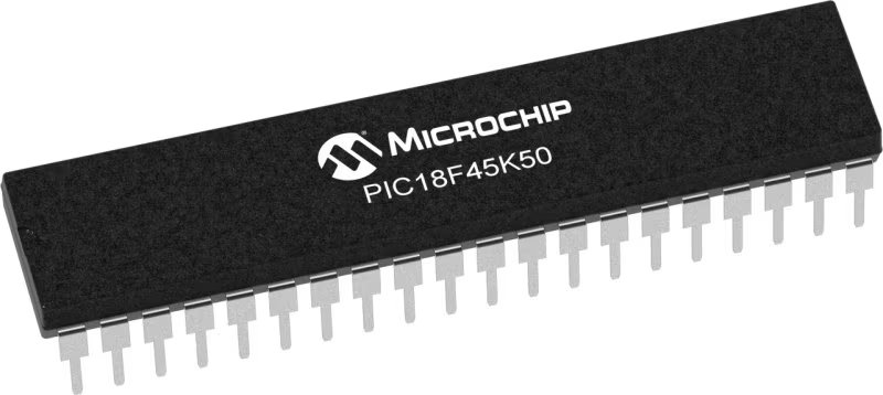
PIC18F45K50
Navigate confidently with the pinnacle of GPS excellence at your fingertips. Our solution blends precision and exploration, ensuring every step of your journey is guided by the highest level of accuracy.
A
A
Hardware Overview
How does it work?
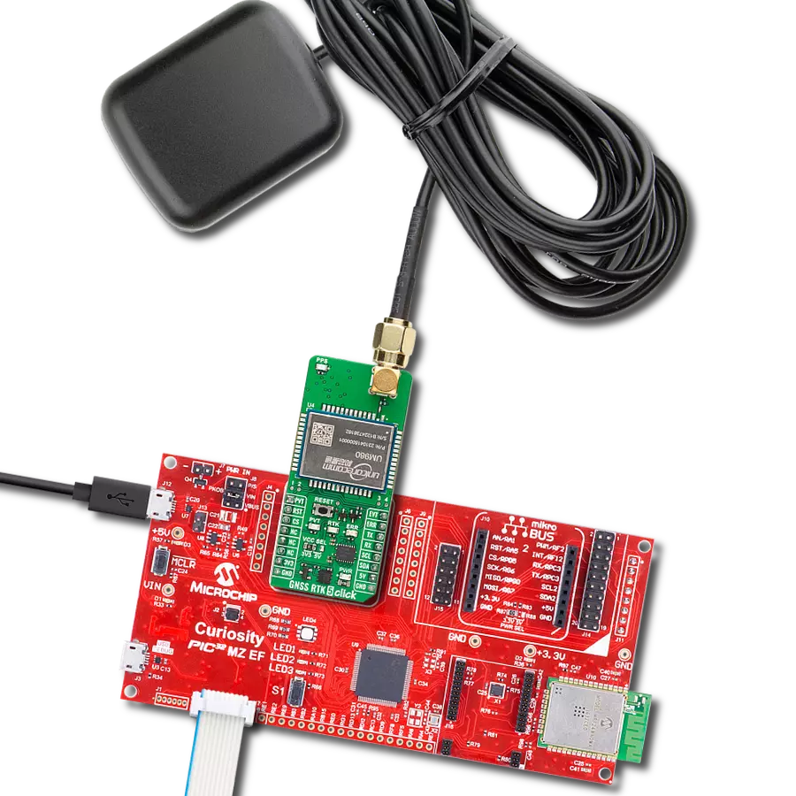
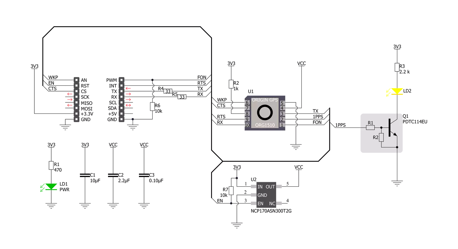
Nano GPS 2 Click uses the Multi Micro Hornet module from OriginGPS, the smallest GPS module with an incorporated on‐board antenna element that is perfectly matched to receiver front‐end, frequency trimmed to GPS band, and Right‐Hand Circularly Polarized (RHCP). Module possesses dual-stage LNA (Low Noise Amplifier), SAW (Surface Acoustic Wave) filter, RTC crystal, GNSS SoC, and RF shield. GNSS SoC on a module is a hybrid positioning processor that combines many constellation configurations to provide a high-performance navigation solution such as GPS, GLONASS, GALILEO, BEIDOU, SBAS, QZSS, DGPS, and AGPS, allowing integration in embedded solutions with low computing resources. The ORG1510-MK05 module supports operational modes that provide positioning information at reduced overall current consumption. The availability of GNSS signals in the operating
environment will also factor in the choice of power management modes. The user can choose a mode that provides the best trade‐off of performance versus power consumption. Several power management modes can be enabled via a command, such as Full Power-Continuous Mode (for best GNSS performance), Power Save Mode (to optimize power consumption), and Backup Mode (low quiescent power state where receiver operation is stopped). Nano GPS 2 Click operates with received signal levels down to ‐167dBm and can be affected by high absolute levels of RF signals out of the GNSS band, moderate levels of RF interference near the GNSS band, and low levels of RF noise in the GNSS band. It uses a standard UART port and, besides the commonly used UART RX, TX, RTS, and CTS Nano GPS 2 Click, also has FON and WKP pins, which are routed to the PWM and AN pins of the mikroBUS™ socket,
respectively. Integrated GPS SoC incorporating a high-performance microprocessor and sophisticated firmware keeps positioning the payload off the host, allowing integration in embedded solutions with low computing resources. Innovative architecture can detect changes in context, temperature, and satellite signals to achieve a state of near-continuous availability by maintaining and opportunistically updating its internal fine time, frequency, and satellite ephemeris data while consuming mere microwatts of battery power. This Click board™ can be operated only with a 3.3V logic voltage level. The board must perform appropriate logic voltage level conversion before using MCUs with different logic levels. Also, it comes equipped with a library containing functions and an example code that can be used as a reference for further development.


Features overview
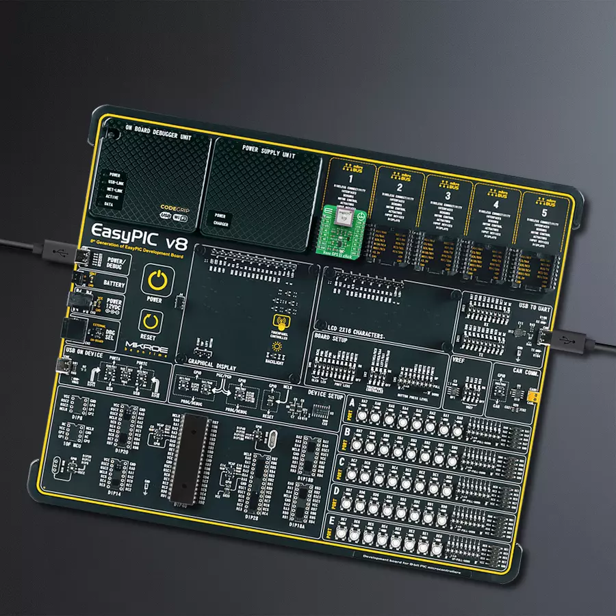
Development board
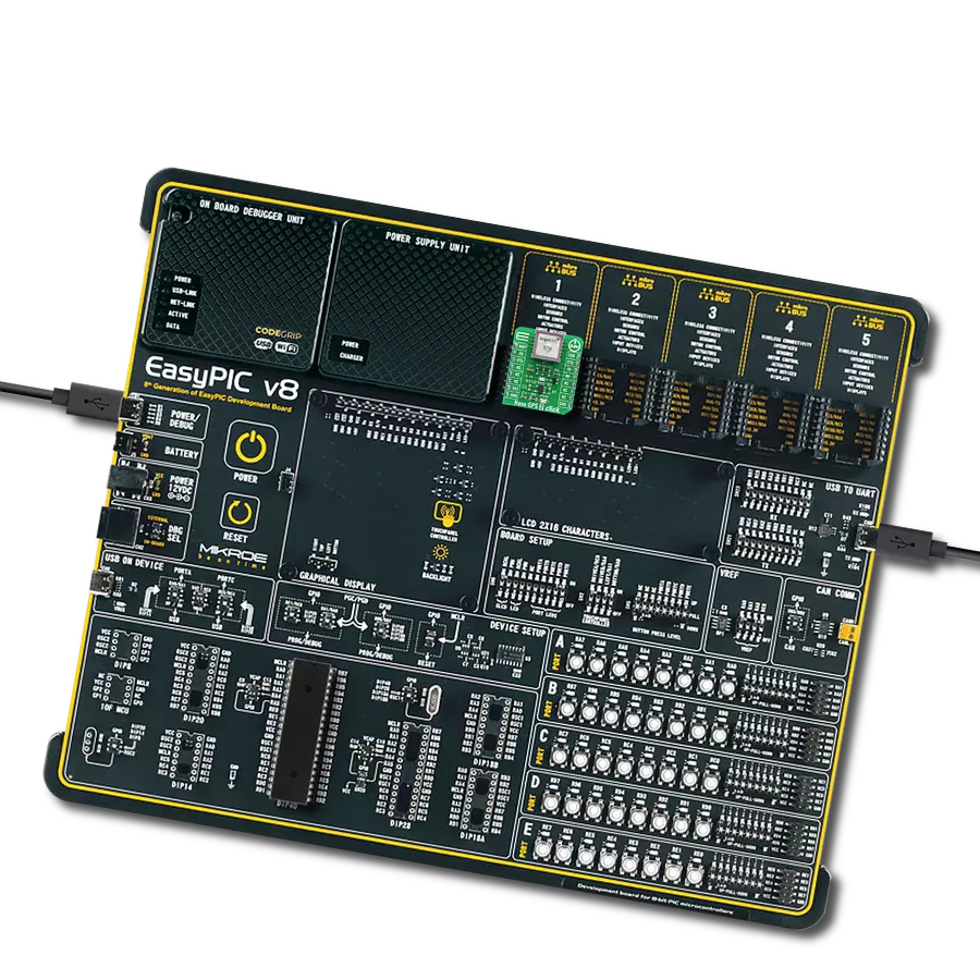
EasyPIC v8 is a development board specially designed for the needs of rapid development of embedded applications. It supports many high pin count 8-bit PIC microcontrollers from Microchip, regardless of their number of pins, and a broad set of unique functions, such as the first-ever embedded debugger/programmer. The development board is well organized and designed so that the end-user has all the necessary elements, such as switches, buttons, indicators, connectors, and others, in one place. Thanks to innovative manufacturing technology, EasyPIC v8 provides a fluid and immersive working experience, allowing access anywhere and under any
circumstances at any time. Each part of the EasyPIC v8 development board contains the components necessary for the most efficient operation of the same board. In addition to the advanced integrated CODEGRIP programmer/debugger module, which offers many valuable programming/debugging options and seamless integration with the Mikroe software environment, the board also includes a clean and regulated power supply module for the development board. It can use a wide range of external power sources, including a battery, an external 12V power supply, and a power source via the USB Type-C (USB-C) connector.
Communication options such as USB-UART, USB DEVICE, and CAN are also included, including the well-established mikroBUS™ standard, two display options (graphical and character-based LCD), and several different DIP sockets. These sockets cover a wide range of 8-bit PIC MCUs, from the smallest PIC MCU devices with only eight up to forty pins. EasyPIC v8 is an integral part of the Mikroe ecosystem for rapid development. Natively supported by Mikroe software tools, it covers many aspects of prototyping and development thanks to a considerable number of different Click boards™ (over a thousand boards), the number of which is growing every day.

Microcontroller Overview
MCU Card / MCU
Architecture
PIC
MCU Memory (KB)
32
Silicon Vendor
Microchip
Pin count
40
RAM (Bytes)
2048
Used MCU Pins
mikroBUS™ mapper
Take a closer look
Click board™ Schematic
Step by step
Project assembly

Start by selecting your development board and Click board™. Begin with the EasyPIC v8 as your development board.


Track your results in real time
Application Output
1. Application Output - In Debug mode, the 'Application Output' window enables real-time data monitoring, offering direct insight into execution results. Ensure proper data display by configuring the environment correctly using the provided tutorial.

2. UART Terminal - Use the UART Terminal to monitor data transmission via a USB to UART converter, allowing direct communication between the Click board™ and your development system. Configure the baud rate and other serial settings according to your project's requirements to ensure proper functionality. For step-by-step setup instructions, refer to the provided tutorial.

3. Plot Output - The Plot feature offers a powerful way to visualize real-time sensor data, enabling trend analysis, debugging, and comparison of multiple data points. To set it up correctly, follow the provided tutorial, which includes a step-by-step example of using the Plot feature to display Click board™ readings. To use the Plot feature in your code, use the function: plot(*insert_graph_name*, variable_name);. This is a general format, and it is up to the user to replace 'insert_graph_name' with the actual graph name and 'variable_name' with the parameter to be displayed.

Software Support
Library Description
This library contains API for Nano GPS 2 Click driver.
Key functions:
nanogps2_set_en_pin_state- Set EN pinnanogps2_module_wakeup- Wake-up modulenanogps2_generic_parser- Generic parser function.
Open Source
Code example
The complete application code and a ready-to-use project are available through the NECTO Studio Package Manager for direct installation in the NECTO Studio. The application code can also be found on the MIKROE GitHub account.
/*!
 * \file
 * \brief NanoGps2 Click example
 *
 * # Description
 * This example reads and processes data from Nano GPS 2 Click.
 *
 * The demo application is composed of two sections :
 *
 * ## Application Init
 * Initializes driver and wake-up module.
 *
 * ## Application Task
 * Reads the received data and parses it.
 *
 * ## Additional Function
 * - nanogps2_process ( ) - The general process of collecting data the module sends.
 *
 * @note
 * Depending on the environmental conditions and the satellites availability
 * it may take some time for the module to receive the position fix.
 *
 * \author MikroE Team
 *
 */
// ------------------------------------------------------------------- INCLUDES

#include "board.h"
#include "log.h"
#include "nanogps2.h"
#include "string.h"

#define PROCESS_COUNTER 10
#define PROCESS_RX_BUFFER_SIZE 600
#define PROCESS_PARSER_BUFFER_SIZE 600

// ------------------------------------------------------------------ VARIABLES

static nanogps2_t nanogps2;
static log_t logger;

static char current_parser_buf[ PROCESS_PARSER_BUFFER_SIZE ];

// ------------------------------------------------------- ADDITIONAL FUNCTIONS

static void nanogps2_process ( void )
{
    int32_t rsp_size;
    uint16_t rsp_cnt = 0;

    char uart_rx_buffer[ PROCESS_RX_BUFFER_SIZE ] = { 0 };
    uint16_t check_buf_cnt;
    uint8_t process_cnt = PROCESS_COUNTER;

    // Clear parser buffer
    memset( current_parser_buf, 0 , PROCESS_PARSER_BUFFER_SIZE );

    while( process_cnt != 0 )
    {
        rsp_size = nanogps2_generic_read( &nanogps2, &uart_rx_buffer, PROCESS_RX_BUFFER_SIZE );

        if ( rsp_size > 0 )
        {
            // Validation of the received data
            for ( check_buf_cnt = 0; check_buf_cnt < rsp_size; check_buf_cnt++ )
            {
                if ( uart_rx_buffer[ check_buf_cnt ] == 0 )
                {
                    uart_rx_buffer[ check_buf_cnt ] = 13;
                }
            }

            // Storages data in parser buffer
            rsp_cnt += rsp_size;
            if ( rsp_cnt < PROCESS_PARSER_BUFFER_SIZE )
            {
                strncat( current_parser_buf, uart_rx_buffer, rsp_size );
            }
            // Clear RX buffer
            memset( uart_rx_buffer, 0, PROCESS_RX_BUFFER_SIZE );
        }
        else
        {
            process_cnt--;

            // Process delay
            Delay_100ms( );
        }
    }
}

static void parser_application ( char *rsp )
{
    char element_buf[ 200 ] = { 0 };

    log_printf( &logger, "\r\n-----------------------\r\n" );
    nanogps2_generic_parser( rsp, NANOGPS2_NEMA_GNGGA, NANOGPS2_GNGGA_LATITUDE, element_buf );
    if ( strlen( element_buf ) > 0 )
    {
        log_printf( &logger, "Latitude:  %.2s degrees, %s minutes \r\n", element_buf, &element_buf[ 2 ] );
        nanogps2_generic_parser( rsp, NANOGPS2_NEMA_GNGGA, NANOGPS2_GNGGA_LONGITUDE, element_buf );
        log_printf( &logger, "Longitude:  %.3s degrees, %s minutes \r\n", element_buf, &element_buf[ 3 ] );
        memset( element_buf, 0, sizeof( element_buf ) );
        nanogps2_generic_parser( rsp, NANOGPS2_NEMA_GNGGA, NANOGPS2_GNGGA_ALTITUDE, element_buf );
        log_printf( &logger, "Altitude: %s m", element_buf );
    }
    else
    {
        log_printf( &logger, "Waiting for the position fix..." );
    }
}

// ------------------------------------------------------ APPLICATION FUNCTIONS

void application_init ( void )
{
    log_cfg_t log_cfg;
    nanogps2_cfg_t cfg;

    /**
     * Logger initialization.
     * Default baud rate: 115200
     * Default log level: LOG_LEVEL_DEBUG
     * @note If USB_UART_RX and USB_UART_TX
     * are defined as HAL_PIN_NC, you will
     * need to define them manually for log to work.
     * See @b LOG_MAP_USB_UART macro definition for detailed explanation.
     */
    LOG_MAP_USB_UART( log_cfg );
    log_init( &logger, &log_cfg );
    log_info( &logger, "---- Application Init ----" );

    //  Click initialization.

    nanogps2_cfg_setup( &cfg );
    NANOGPS2_MAP_MIKROBUS( cfg, MIKROBUS_1 );
    nanogps2_init( &nanogps2, &cfg );

    nanogps2_module_wakeup ( &nanogps2 );
}

void application_task ( void )
{
    nanogps2_process( );
    parser_application( current_parser_buf );
}

int main ( void )
{
    /* Do not remove this line or clock might not be set correctly. */
    #ifdef PREINIT_SUPPORTED
    preinit();
    #endif

    application_init( );

    for ( ; ; )
    {
        application_task( );
    }

    return 0;
}

// ------------------------------------------------------------------------ END