Elevate your GNSS experience with PIC32MZ1024EFH064 and L89H, an IRNSS-enabled multi-constellation solution
Navigate limitless horizons

Published Sep 02, 2023
Click board™
IRNSS Click
Dev. board
PIC32MZ clicker
Compiler
NECTO Studio
MCU
PIC32MZ1024EFH064
Our high-performance GNSS solution, empowered by integrated IRNSS technology, goes beyond boundaries in redefining navigation accuracy. Experience confidence in each coordinate, knowing that precision is at the heart of your journey.
A
A
Hardware Overview
How does it work?
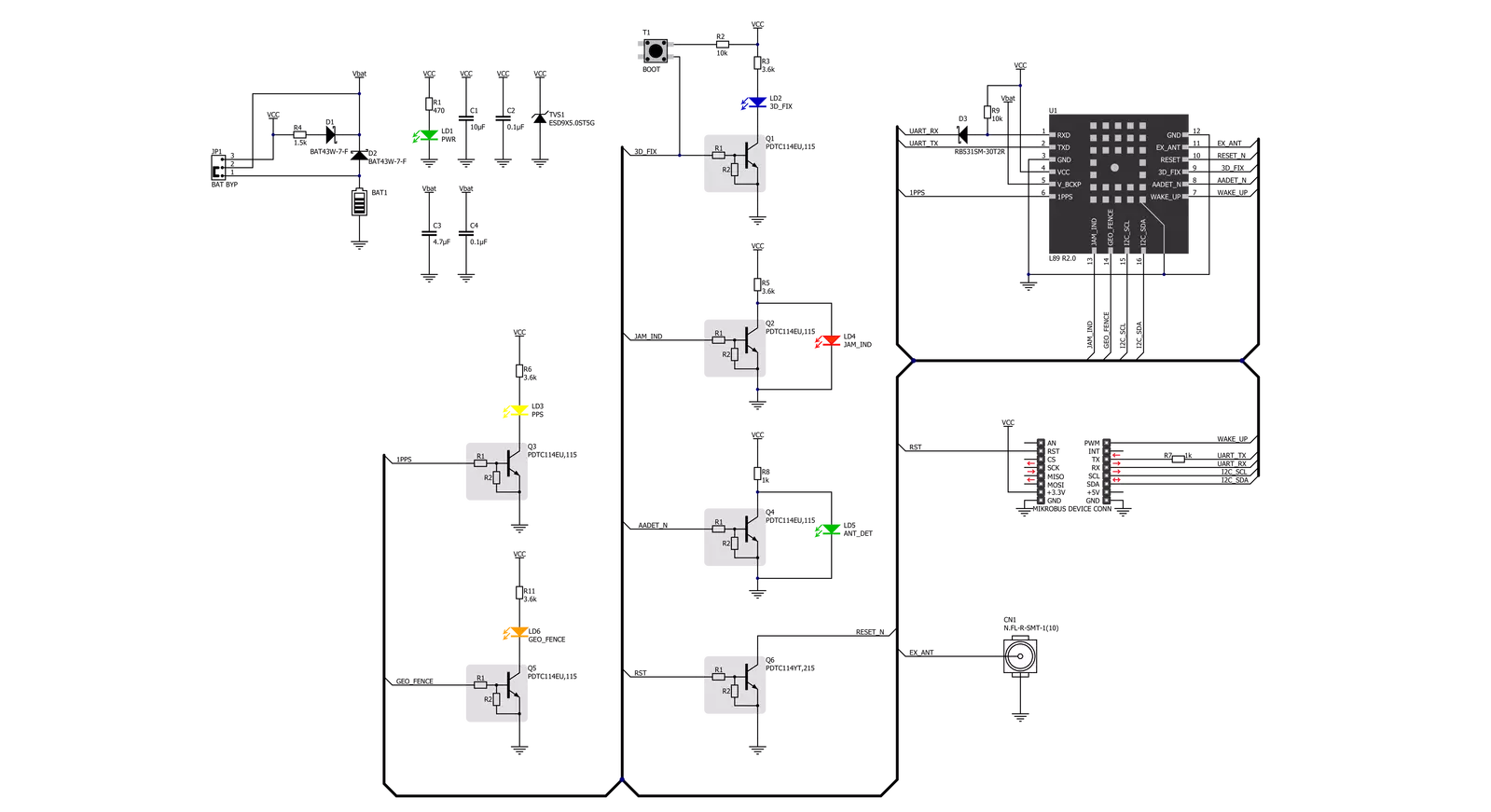
IRNSS Click is based on the L89H, a high-performance acquiring and tracking IRNSS-enabled GNSS module from Quectel Wireless Solutions. It achieves a high industrial level of sensitivity, accuracy, and TTFF with low power consumption. The embedded flash memory provides a capacity for storing user-specific configurations and allows for future updates. It is fully compliant with the EU RoHS directive supporting multiple positioning and navigation systems, including autonomous GPS, BeiDou, GLONASS, Galileo, IRNSS, SBAS (including WAAS, EGNOS, MSAS, and GAGAN), QZSS, DGPS, and AGPS. IRNSS Click provides the possibility of using both UART and I2C interfaces. The UART interface supports data baud rates from 4800bps to 921600bps, with 921600bps by default, while the I2C interface supports a fast mode of operation with a bit rate up to 400kbps. Alongside interface pins, this Click board™ also has a Reset feature routed to the RST pin on the mikroBUS™ socket, which, with a low logic level, puts the module into a Reset state and, with a high level, operates the
module normally. It also has a Wake-Up feature, routed to the PWM pin on the mikroBUS™ socket, forcing the module to wake up from Backup mode. This Click board™ uses five different LED indicators available for signal indication. Blue LED labeled as 3D_FIX turns on to indicate successful positioning after the L89H module is turned on. Yellow LED labeled as PPS indicates one pulse synchronized to GNSS satellites per second. Remember that PPS can be held even after losing the satellite signal by the internal RTC. The Red LED labeled as JAM_IND represents a jamming detection indicator to detect whether any jammers may have an impact on the module. Green LED labeled as ANT_DET indicates active antenna status - Orange LED labeled as GEO_FENCE indicates whether the module enters or exits the geo-fence. The module can use a backup supply voltage from a connected battery in the primary power supply failure case. IRNSS Click can use an externally chargeable battery from the button cell battery holder, suitable for 12mm Coin Cell batteries if the SMD jumper
labeled as BAT BYP is positioned to a position marked as CHG for uninterrupted operation. Otherwise, when the jumper is in a position labeled as BRD, the module is powered only by 3.3V from the board, and if the jumper is not even populated, then the module is powered from a non-chargeable battery. The L89H module can be connected to a dedicated passive or active GNSS antenna with a built-in LNA for sensitivity improvement. IRNSS Click possesses a miniature coaxial N.FL series antenna connector, which, combined with IPEX-SMA cable, allows connecting the appropriate antenna, such as GNSS Active External Antenna or other external antennas from our offer for improved range and received signal strength. This Click board™ can be operated only with a 3.3V logic voltage level. The board must perform appropriate logic voltage level conversion before using MCUs with different logic levels. Also, it comes equipped with a library containing functions and an example code that can be used as a reference for further development.

Features overview
Development board
PIC32MZ Clicker is a compact starter development board that brings the flexibility of add-on Click boards™ to your favorite microcontroller, making it a perfect starter kit for implementing your ideas. It comes with an onboard 32-bit PIC32MZ microcontroller with FPU from Microchip, a USB connector, LED indicators, buttons, a mikroProg connector, and a header for interfacing with external electronics. Thanks to its compact design with clear and easy-recognizable silkscreen markings, it provides a fluid and immersive working experience, allowing access anywhere and under
any circumstances. Each part of the PIC32MZ Clicker development kit contains the components necessary for the most efficient operation of the same board. In addition to the possibility of choosing the PIC32MZ Clicker programming method, using USB HID mikroBootloader, or through an external mikroProg connector for PIC, dsPIC, or PIC32 programmer, the Clicker board also includes a clean and regulated power supply module for the development kit. The USB Micro-B connection can provide up to 500mA of current, which is more than enough to operate all onboard
and additional modules. All communication methods that mikroBUS™ itself supports are on this board, including the well-established mikroBUS™ socket, reset button, and several buttons and LED indicators. PIC32MZ Clicker is an integral part of the Mikroe ecosystem, allowing you to create a new application in minutes. Natively supported by Mikroe software tools, it covers many aspects of prototyping thanks to a considerable number of different Click boards™ (over a thousand boards), the number of which is growing every day.

Microcontroller Overview
MCU Card / MCU

Architecture
PIC32
MCU Memory (KB)
1024
Silicon Vendor
Microchip
Pin count
64
RAM (Bytes)
524288
Used MCU Pins
mikroBUS™ mapper
Take a closer look
Click board™ Schematic
Step by step
Project assembly

Start by selecting your development board and Click board™. Begin with the PIC32MZ clicker as your development board.


Track your results in real time
Application Output
1. Application Output - In Debug mode, the 'Application Output' window enables real-time data monitoring, offering direct insight into execution results. Ensure proper data display by configuring the environment correctly using the provided tutorial.

2. UART Terminal - Use the UART Terminal to monitor data transmission via a USB to UART converter, allowing direct communication between the Click board™ and your development system. Configure the baud rate and other serial settings according to your project's requirements to ensure proper functionality. For step-by-step setup instructions, refer to the provided tutorial.

3. Plot Output - The Plot feature offers a powerful way to visualize real-time sensor data, enabling trend analysis, debugging, and comparison of multiple data points. To set it up correctly, follow the provided tutorial, which includes a step-by-step example of using the Plot feature to display Click board™ readings. To use the Plot feature in your code, use the function: plot(*insert_graph_name*, variable_name);. This is a general format, and it is up to the user to replace 'insert_graph_name' with the actual graph name and 'variable_name' with the parameter to be displayed.

Software Support
Library Description
This library contains API for IRNSS Click driver.
Key functions:
irnss_set_rst_pin_state- This function sets rst pin output to state settingirnss_generic_read- This function reads a desired number of data bytes by using UART serial interfaceirnss_parse_gngga- This function parses the GNGGA data from the read response buffer
Open Source
Code example
The complete application code and a ready-to-use project are available through the NECTO Studio Package Manager for direct installation in the NECTO Studio. The application code can also be found on the MIKROE GitHub account.
/*!
 * @file main.c
 * @brief IRNSS Click Example.
 *
 * # Description
 * This example demonstrates the use of IRNSS Click by reading and displaying
 * the GPS coordinates.
 *
 * The demo application is composed of two sections :
 *
 * ## Application Init
 * Initializes the driver and resets the Click board.
 *
 * ## Application Task
 * Reads the received data, parses the GNGGA info from it, and once it receives the position fix
 * it will start displaying the coordinates on the USB UART.
 *
 * ## Additional Function
 * - static void irnss_clear_app_buf ( void )
 * - static err_t irnss_process ( irnss_t *ctx )
 * - static void irnss_parser_application ( char *rsp )
 *
 * @author Stefan Filipovic
 *
 */

#include "board.h"
#include "log.h"
#include "irnss.h"

#define PROCESS_BUFFER_SIZE 200

static irnss_t irnss;
static log_t logger;

static char app_buf[ PROCESS_BUFFER_SIZE ] = { 0 };
static int32_t app_buf_len = 0;
static int32_t app_buf_cnt = 0;

/**
 * @brief IRNSS clearing application buffer.
 * @details This function clears memory of application buffer and reset its length and counter.
 * @return None.
 * @note None.
 */
static void irnss_clear_app_buf ( void );

/**
 * @brief IRNSS data reading function.
 * @details This function reads data from device and concatenates data to application buffer.
 * @param[in] ctx : Click context object.
 * See #irnss_t object definition for detailed explanation.
 * @return @li @c  0 - Read some data.
 *         @li @c -1 - Nothing is read or Application buffer overflow.
 * See #err_t definition for detailed explanation.
 * @note None.
 */
static err_t irnss_process ( irnss_t *ctx );

/**
 * @brief IRNSS parser application.
 * @param[in] rsp Response buffer.
 * @details This function logs GNSS data on the USB UART.
 * @return None.
 * @note None.
 */
static void irnss_parser_application ( char *rsp );

void application_init ( void )
{
    log_cfg_t log_cfg;  /**< Logger config object. */
    irnss_cfg_t irnss_cfg;  /**< Click config object. */

    /**
     * Logger initialization.
     * Default baud rate: 115200
     * Default log level: LOG_LEVEL_DEBUG
     * @note If USB_UART_RX and USB_UART_TX
     * are defined as HAL_PIN_NC, you will
     * need to define them manually for log to work.
     * See @b LOG_MAP_USB_UART macro definition for detailed explanation.
     */
    LOG_MAP_USB_UART( log_cfg );
    log_init( &logger, &log_cfg );
    log_info( &logger, " Application Init " );

    // Click initialization.
    irnss_cfg_setup( &irnss_cfg );
    IRNSS_MAP_MIKROBUS( irnss_cfg, MIKROBUS_1 );
    if ( UART_ERROR == irnss_init( &irnss, &irnss_cfg ) )
    {
        log_error( &logger, " Communication init." );
        for ( ; ; );
    }
    log_info( &logger, " Application Task " );
}

void application_task ( void )
{
    irnss_process( &irnss );
    if ( app_buf_len > ( sizeof ( ( char * ) IRNSS_RSP_GNGGA ) + IRNSS_GNGGA_ELEMENT_SIZE ) )
    {
        irnss_parser_application( app_buf );
    }
}

int main ( void )
{
    /* Do not remove this line or clock might not be set correctly. */
    #ifdef PREINIT_SUPPORTED
    preinit();
    #endif

    application_init( );

    for ( ; ; )
    {
        application_task( );
    }

    return 0;
}

static void irnss_clear_app_buf ( void )
{
    memset( app_buf, 0, app_buf_len );
    app_buf_len = 0;
    app_buf_cnt = 0;
}

static err_t irnss_process ( irnss_t *ctx )
{
    int32_t rx_size = 0;
    char rx_buf[ PROCESS_BUFFER_SIZE ] = { 0 };
    rx_size = irnss_generic_read( ctx, rx_buf, PROCESS_BUFFER_SIZE );
    if ( rx_size > 0 )
    {
        int32_t buf_cnt = 0;
        if ( ( app_buf_len + rx_size ) > PROCESS_BUFFER_SIZE )
        {
            irnss_clear_app_buf(  );
            return IRNSS_ERROR;
        }
        else
        {
            buf_cnt = app_buf_len;
            app_buf_len += rx_size;
        }
        for ( int32_t rx_cnt = 0; rx_cnt < rx_size; rx_cnt++ )
        {
            if ( rx_buf[ rx_cnt ] )
            {
                app_buf[ ( buf_cnt + rx_cnt ) ] = rx_buf[ rx_cnt ];
            }
            else
            {
                app_buf_len--;
                buf_cnt--;
            }
        }
        return IRNSS_OK;
    }
    return IRNSS_ERROR;
}

static void irnss_parser_application ( char *rsp )
{
    char element_buf[ 100 ] = { 0 };
    if ( IRNSS_OK == irnss_parse_gngga( rsp, IRNSS_GNGGA_LATITUDE, element_buf ) )
    {
        static uint8_t wait_for_fix_cnt = 0;
        if ( strlen( element_buf ) > 0 )
        {
            log_printf( &logger, "\r\n Latitude: %.2s degrees, %s minutes \r\n", element_buf, &element_buf[ 2 ] );
            irnss_parse_gngga( rsp, IRNSS_GNGGA_LONGITUDE, element_buf );
            log_printf( &logger, " Longitude: %.3s degrees, %s minutes \r\n", element_buf, &element_buf[ 3 ] );
            memset( element_buf, 0, sizeof( element_buf ) );
            irnss_parse_gngga( rsp, IRNSS_GNGGA_ALTITUDE, element_buf );
            log_printf( &logger, " Altitude: %s m \r\n", element_buf );
            wait_for_fix_cnt = 0;
        }
        else
        {
            if ( wait_for_fix_cnt % 5 == 0 )
            {
                log_printf( &logger, " Waiting for the position fix...\r\n\n" );
                wait_for_fix_cnt = 0;
            }
            wait_for_fix_cnt++;
        }
        irnss_clear_app_buf(  );
    }
}

// ------------------------------------------------------------------------ END


