Unleash the potential of brushless motors with TB6575FNG and PIC18F47K42
Seamless motion, limitless power
Published Jul 26, 2023
Click board™
Brushless Click
Dev. board
EasyPIC v8
Compiler
NECTO Studio
MCU
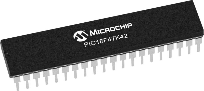
PIC18F47K42
Empower robotics, drones, and automation applications with reliable and efficient motion control
A
A
Hardware Overview
How does it work?
Brushless Click is based on the TB6575FNG, a PWM sensorless controller for three-phase full-wave BLDC from Toshiba Semiconductor. It is based on the PWM chopper drive. After receiving an analog voltage command input, the rotor is aligned to a known position, and then the rotation is started in a forced commutation mode, thus acquiring the back-EMF. To drive a BLDC motor in a sensorless drive, a signal is generated based on the back-EMF sensing as a natural commutation PWM signal. This natural commutation PWM is automatically switched from the forced Commutation PWM signal when a polarity signal of each phase voltage (including the back-EMF) is applied to the position signal input. Two types of MOSFET chips onboard switch the output ON and OFF. This controls the voltage levels applied to the motor, determining the motor shaft's speed and rotation. These are the Si4497, a P-channel 30V MOSFET, and the Si4154, an N-channel 40V MOSFET from Vishay. Brushless click is
theoretically capable of outputting higher currents; however, in such a case, the MOSFET chips have to be cooled down with an external cooler. To connect an external DC power supply, there is a VBAT screw terminal. The screw terminal labeled BLDC (GND, U, V, W) is for connecting phases of an external motor. As a position sensing input of the TB6575FNG, this Click board™ uses the LM2903, a low-power dual voltage comparator from STMicroelectronics. For sensing purposes, this comparator uses voltages of all motor driver outputs. For a duty cycle control input, this Click board™ uses the MCP6281, a rail-to-rail operational amplifier from Microchip. This OpAmp as input uses a PWM signal from the mikroBUS™ socket. Brushless Click uses only a PWM signal as a connection with the host MCU over the mikroBUS™ socket. The signal is supplied to the WAVE position sensing input of the motor driver through the operational amplifier. The rotation speed sensing output is monitored over the INT
pin of the mikroBUS™ socket. To set the rotation direction, you can use logic HIGH and LOW states on the DIR pin, HIGH for reverse, and LOW for forward rotation. The VSN pin over the resistor divider can monitor the battery voltage. Position detection is synchronized with the PWM signal generated in the IC. A position detection error relative to the PWM frequency may occur when the IC is used in a high-speed motor. The detection is performed on the falling edge of the PWM signal. An error is recognized when the pin voltage exceeds the reference voltage. This Click board™ can be operated only with a 5V logic voltage level. The board must perform appropriate logic voltage level conversion before using MCUs with different logic levels. It comes equipped with a library containing functions and an example code that can be used, as a reference, for further development.

Features overview
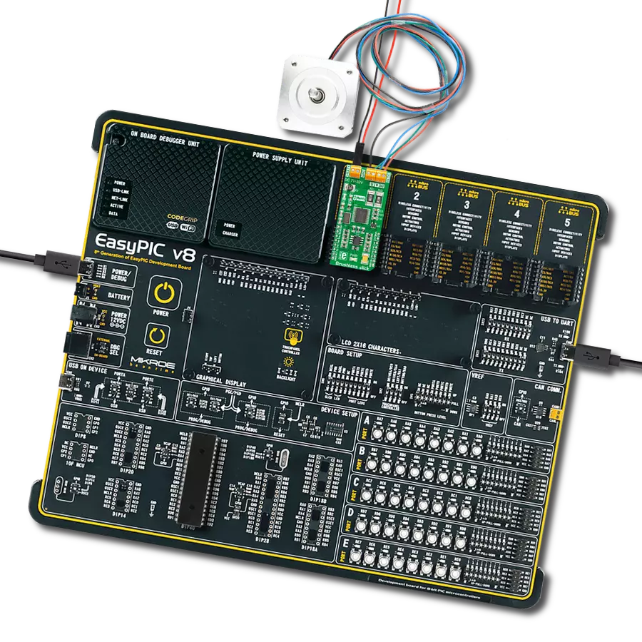
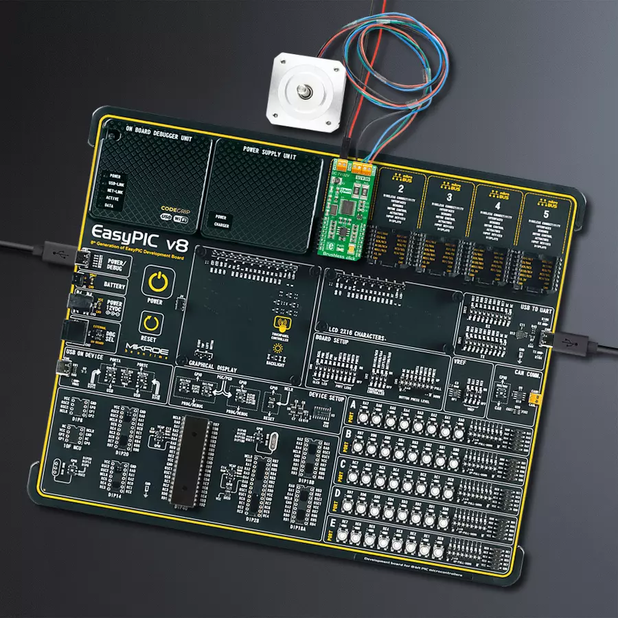
Development board
EasyPIC v8 is a development board specially designed for the needs of rapid development of embedded applications. It supports many high pin count 8-bit PIC microcontrollers from Microchip, regardless of their number of pins, and a broad set of unique functions, such as the first-ever embedded debugger/programmer. The development board is well organized and designed so that the end-user has all the necessary elements, such as switches, buttons, indicators, connectors, and others, in one place. Thanks to innovative manufacturing technology, EasyPIC v8 provides a fluid and immersive working experience, allowing access anywhere and under any
circumstances at any time. Each part of the EasyPIC v8 development board contains the components necessary for the most efficient operation of the same board. In addition to the advanced integrated CODEGRIP programmer/debugger module, which offers many valuable programming/debugging options and seamless integration with the Mikroe software environment, the board also includes a clean and regulated power supply module for the development board. It can use a wide range of external power sources, including a battery, an external 12V power supply, and a power source via the USB Type-C (USB-C) connector.
Communication options such as USB-UART, USB DEVICE, and CAN are also included, including the well-established mikroBUS™ standard, two display options (graphical and character-based LCD), and several different DIP sockets. These sockets cover a wide range of 8-bit PIC MCUs, from the smallest PIC MCU devices with only eight up to forty pins. EasyPIC v8 is an integral part of the Mikroe ecosystem for rapid development. Natively supported by Mikroe software tools, it covers many aspects of prototyping and development thanks to a considerable number of different Click boards™ (over a thousand boards), the number of which is growing every day.

Microcontroller Overview
MCU Card / MCU
Architecture
PIC
MCU Memory (KB)
128
Silicon Vendor
Microchip
Pin count
40
RAM (Bytes)
8192
You complete me!
Accessories
Brushless DC (BLDC) Motor with a Hall sensor represents a high-performance motor from the 42BLF motor series. This motor, wired in a star configuration, boasts a Hall Effect angle of 120°, ensuring precise and reliable performance. With a compact motor length of 47mm and a lightweight design tipping the scales at just 0.29kg, this BLDC motor is engineered to meet your needs. Operating flawlessly at a voltage rating of 24VDC and a speed range of 4000 ± 10% RPM, this motor offers consistent and dependable power. It excels in a normal operational temperature range from -20 to +50°C, maintaining efficiency with a rated current of 1.9A. Also, this product seamlessly integrates with all Brushless Click boards™ and those that require BLDC motors with Hall sensors.

Used MCU Pins
mikroBUS™ mapper
Take a closer look
Click board™ Schematic

Step by step
Project assembly

Start by selecting your development board and Click board™. Begin with the EasyPIC v8 as your development board.


Software Support
Library Description
This library contains API for Brushless Click driver.
Key functions:
brushless_spin_clockwise- This function sets the spin direction of the motor to clockwisebrushless_spin_counter_clockwise-This function sets the spin direction of the motor to counter clockwisebrushless_read_rotation_speed_sensor_output- This function reads the digital input of the INT pin
Open Source
Code example
The complete application code and a ready-to-use project are available through the NECTO Studio Package Manager for direct installation in the NECTO Studio. The application code can also be found on the MIKROE GitHub account.
/*!
 * \file
 * \brief Brushless Click example
 *
 * # Description
 * This example showcases how to initialize and use the Brushless Click.
 * The Click has a brushless motor driver which controls the work
 * of the motor through the BLDC terminal.
 * In order for this example to work a motor and a power supply are needed.
 *
 * The demo application is composed of two sections :
 *
 * ## Application Init
 * This function initializes and configures the logger and Click modules.
 *
 * ## Application Task
 * This is an example that demonstrates the use of a Brushless Click board.
 * Brushless Click communicates with the register via the PWM interface.
 * It shows moving in the left direction from slow to fast speed
 * and from fast to slow speed.
 * Results are being sent to the Usart Terminal where you can track their changes.
 *
 * \author Nikola Peric
 *
 */
// ------------------------------------------------------------------- INCLUDES

#include "board.h"
#include "log.h"
#include "brushless.h"

// ------------------------------------------------------------------ VARIABLES

static brushless_t brushless;
static log_t logger;
uint8_t brushless_direction = 1;

// ------------------------------------------------------ APPLICATION FUNCTIONS

void application_init ( )
{
    log_cfg_t log_cfg;
    brushless_cfg_t cfg;

    /**
     * Logger initialization.
     * Default baud rate: 115200
     * Default log level: LOG_LEVEL_DEBUG
     * @note If USB_UART_RX and USB_UART_TX
     * are defined as HAL_PIN_NC, you will
     * need to define them manually for log to work.
     * See @b LOG_MAP_USB_UART macro definition for detailed explanation.
     */
    LOG_MAP_USB_UART( log_cfg );
    log_init( &logger, &log_cfg );
    log_info( &logger, "---- Application Init ----" );
    Delay_ms ( 100 );

    //  Click initialization.
    brushless_cfg_setup( &cfg );
    BRUSHLESS_MAP_MIKROBUS( cfg, MIKROBUS_1 );
    Delay_ms ( 100 );

    brushless_init( &brushless, &cfg );
    brushless_pwm_start( &brushless );
    log_info( &logger, "---- Application Task ----" );
    Delay_ms ( 1000 );
}

void application_task ( )
{
    static int8_t duty_cnt = 1;
    static int8_t duty_inc = 1;
    float duty = duty_cnt / 10.0;

    if ( brushless_direction == 1 )
    {
        brushless_spin_clockwise ( &brushless );
        log_printf( &logger, "<<<< " );
    }
    else
    {
        brushless_spin_counter_clockwise ( &brushless );
        log_printf( &logger, ">>>> " );
    }

    brushless_set_duty_cycle ( &brushless, duty );
    log_printf( &logger, "Duty: %d%%\r\n", ( uint16_t )( duty_cnt * 10 ) );
    Delay_ms ( 500 );

    if ( 10 == duty_cnt )
    {
        duty_inc = -1;
    }
    else if ( 0 == duty_cnt )
    {
        duty_inc = 1;

        if ( brushless_direction == 1 )
        {
            brushless_direction = 0;
        }
        else if ( brushless_direction == 0 )
        {
            brushless_direction = 1;
        }
    }
    duty_cnt += duty_inc;
}

int main ( void )
{
    /* Do not remove this line or clock might not be set correctly. */
    #ifdef PREINIT_SUPPORTED
    preinit();
    #endif

    application_init( );

    for ( ; ; )
    {
        application_task( );
    }

    return 0;
}

// ------------------------------------------------------------------------ END


