Simplify signal routing and control with TCA9536 and PIC18F45K40
Connect with confidence: Bidirectional I/O brilliance!
Published Oct 07, 2023
Click board™
Expand 11 Click
Dev. board
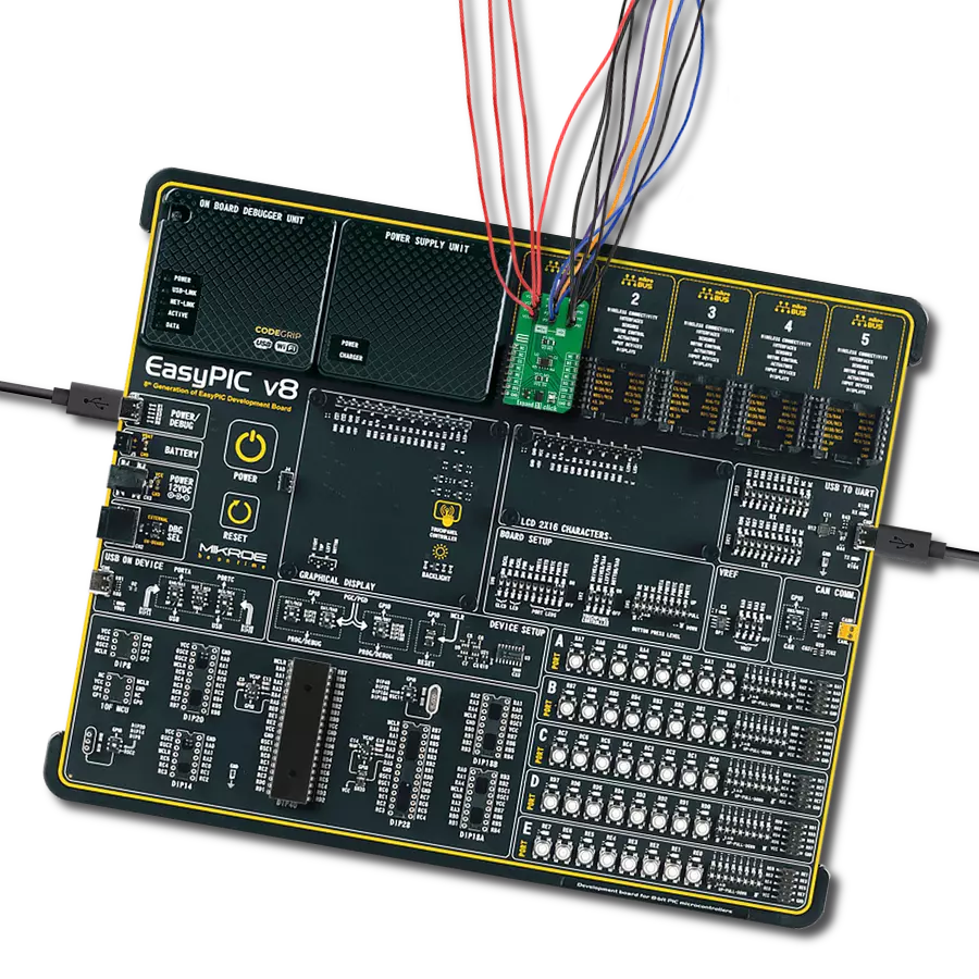
EasyPIC v8
Compiler
NECTO Studio
MCU
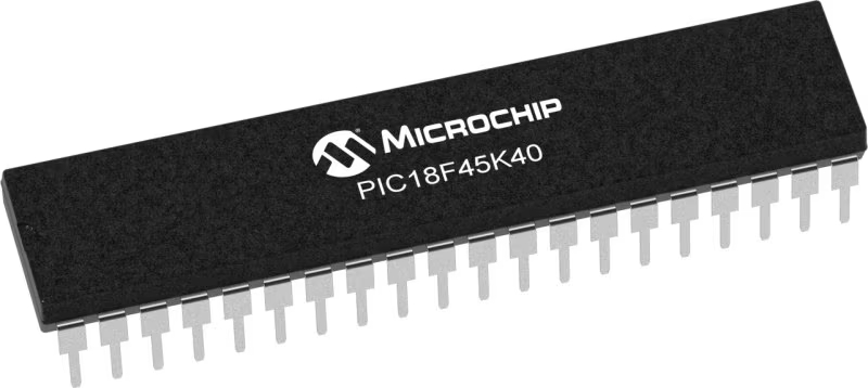
PIC18F45K40
Experience effortless I/O expansion and data management across a wide range of applications, from smart home devices to sensor networks, with our versatile and bi-directional I/O expander
A
A
Hardware Overview
How does it work?
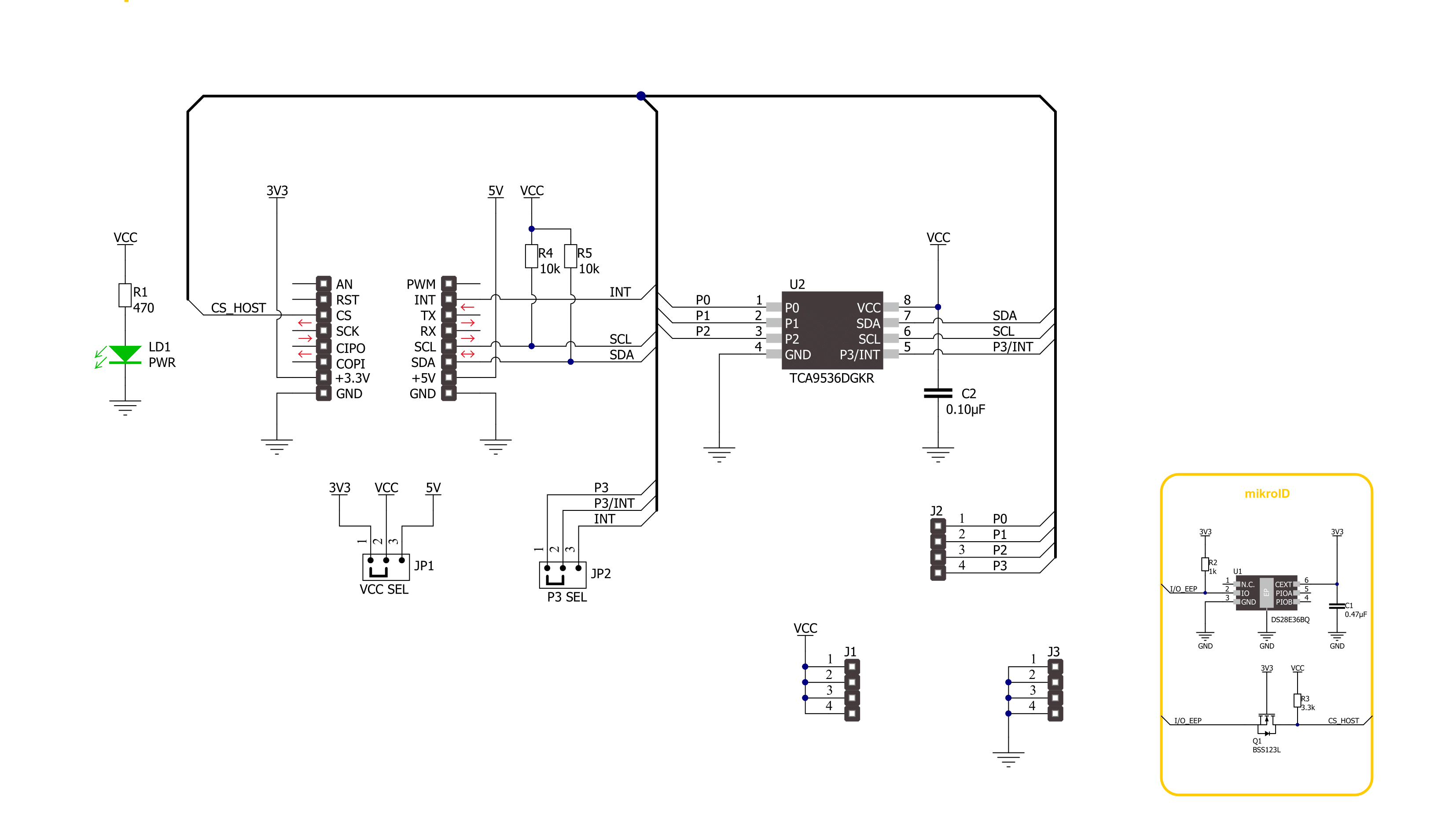
Expand 11 Click is based on the TCA9536, a general-purpose I/O expander from Texas Instruments. It contains four 4-bit configuration ports alongside an I2C-compatible serial interface. Any four I/Os can be configured by the host MCU as an input or output by writing to the configuration register. During the Power-On sequence, the I/Os are configured as inputs with a weak pull-up to the selected mikroBUS™ power rail. The data for each input or output is kept in the corresponding register. The polarity of the Input Port register can be inverted with the Polarity Inversion register. The
TCA9536 outputs (latched) have high-current drive capability for directly driving LEDs. This Click board™ communicates with MCU using the standard I2C 2-Wire interface to read data and configure settings with a maximum frequency of 1MHz. The Expand 11 Click can also select the function of one of the ports, the P3 port, between its standard I/O and interrupt function. The selection is made by positioning SMD jumpers labeled P3 SEL in an appropriate position marked as I/O or INT. In addition to the jumper setting to the proper place, this function must also be set
in the special function register to turn off the internal pull-up resistors and P3 override to an INT output. This Click board™ can operate with either 3.3V or 5V logic voltage levels selected via the VCC SEL jumper. This way, both 3.3V and 5V capable MCUs can use the communication lines properly. Also, this Click board™ comes equipped with a library containing easy-to-use functions and an example code that can be used as a reference for further development.


Features overview
Development board
EasyPIC v8 is a development board specially designed for the needs of rapid development of embedded applications. It supports many high pin count 8-bit PIC microcontrollers from Microchip, regardless of their number of pins, and a broad set of unique functions, such as the first-ever embedded debugger/programmer. The development board is well organized and designed so that the end-user has all the necessary elements, such as switches, buttons, indicators, connectors, and others, in one place. Thanks to innovative manufacturing technology, EasyPIC v8 provides a fluid and immersive working experience, allowing access anywhere and under any
circumstances at any time. Each part of the EasyPIC v8 development board contains the components necessary for the most efficient operation of the same board. In addition to the advanced integrated CODEGRIP programmer/debugger module, which offers many valuable programming/debugging options and seamless integration with the Mikroe software environment, the board also includes a clean and regulated power supply module for the development board. It can use a wide range of external power sources, including a battery, an external 12V power supply, and a power source via the USB Type-C (USB-C) connector.
Communication options such as USB-UART, USB DEVICE, and CAN are also included, including the well-established mikroBUS™ standard, two display options (graphical and character-based LCD), and several different DIP sockets. These sockets cover a wide range of 8-bit PIC MCUs, from the smallest PIC MCU devices with only eight up to forty pins. EasyPIC v8 is an integral part of the Mikroe ecosystem for rapid development. Natively supported by Mikroe software tools, it covers many aspects of prototyping and development thanks to a considerable number of different Click boards™ (over a thousand boards), the number of which is growing every day.

Microcontroller Overview
MCU Card / MCU
Architecture
PIC
MCU Memory (KB)
32
Silicon Vendor
Microchip
Pin count
40
RAM (Bytes)
2048
Used MCU Pins
mikroBUS™ mapper
Take a closer look
Click board™ Schematic
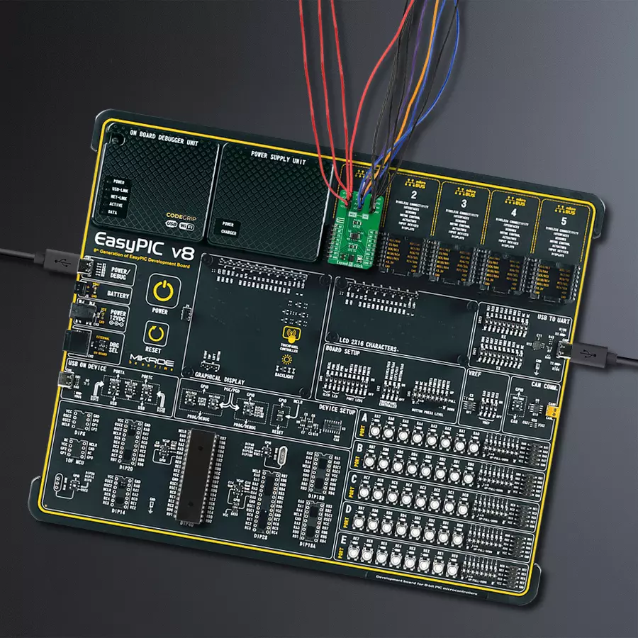
Step by step
Project assembly

Start by selecting your development board and Click board™. Begin with the EasyPIC v8 as your development board.


Software Support
Library Description
This library contains API for Expand 11 Click driver.
Key functions:
expand11_set_pin_direction- This function sets the direction of the selected pinsexpand11_set_all_pins_value- This function sets the value of all output pinsexpand11_read_port_value- This function reads the value of the port input pins
Open Source
Code example
The complete application code and a ready-to-use project are available through the NECTO Studio Package Manager for direct installation in the NECTO Studio. The application code can also be found on the MIKROE GitHub account.
/*!
 * @file main.c
 * @brief Expand 11 Click example
 *
 * # Description
 * This example demonstrates the use of Expand 11 Click board by setting and
 * reading the port state.
 *
 * The demo application is composed of two sections :
 *
 * ## Application Init
 * Initializes the driver and performs the Click default configuration which sets
 * the pins P0-P1 as output and P2-P3 as input.
 *
 * ## Application Task
 * Toggles all output pins and then reads the status of the whole port and
 * displays the results on the USB UART approximately once per second.
 *
 * @author Stefan Filipovic
 *
 */

#include "board.h"
#include "log.h"
#include "expand11.h"

static expand11_t expand11;
static log_t logger;

void application_init ( void )
{
    log_cfg_t log_cfg;  /**< Logger config object. */
    expand11_cfg_t expand11_cfg;  /**< Click config object. */

    /**
     * Logger initialization.
     * Default baud rate: 115200
     * Default log level: LOG_LEVEL_DEBUG
     * @note If USB_UART_RX and USB_UART_TX
     * are defined as HAL_PIN_NC, you will
     * need to define them manually for log to work.
     * See @b LOG_MAP_USB_UART macro definition for detailed explanation.
     */
    LOG_MAP_USB_UART( log_cfg );
    log_init( &logger, &log_cfg );
    log_info( &logger, " Application Init " );

    // Click initialization.
    expand11_cfg_setup( &expand11_cfg );
    EXPAND11_MAP_MIKROBUS( expand11_cfg, MIKROBUS_1 );
    if ( I2C_MASTER_ERROR == expand11_init( &expand11, &expand11_cfg ) )
    {
        log_error( &logger, " Communication init." );
        for ( ; ; );
    }

    if ( EXPAND11_ERROR == expand11_default_cfg ( &expand11 ) )
    {
        log_error( &logger, " Default configuration." );
        for ( ; ; );
    }

    log_info( &logger, " Application Task " );
}

void application_task ( void )
{
    static uint16_t pin_num = EXPAND11_PIN_0_MASK;
    uint8_t port_value = 0;
    if ( EXPAND11_OK == expand11_set_all_pins_value( &expand11, pin_num ) )
    {
        if ( EXPAND11_OK == expand11_read_port_value( &expand11, &port_value ) )
        {
            log_printf( &logger, " PORT STATUS \r\n" );
            log_printf( &logger, "  P0: %u\r\n", ( uint16_t ) ( port_value & EXPAND11_PIN_0_MASK ) );
            log_printf( &logger, "  P1: %u\r\n", ( uint16_t ) ( ( port_value & EXPAND11_PIN_1_MASK ) >> 1 ) );
            log_printf( &logger, "  P2: %u\r\n", ( uint16_t ) ( ( port_value & EXPAND11_PIN_2_MASK ) >> 2 ) );
            log_printf( &logger, "  P3: %u\r\n\n", ( uint16_t ) ( ( port_value & EXPAND11_PIN_3_MASK ) >> 3 ) );
            pin_num = ( ~pin_num ) & EXPAND11_ALL_PINS_MASK;
        }
    }
    Delay_ms ( 1000 );
}

int main ( void )
{
    /* Do not remove this line or clock might not be set correctly. */
    #ifdef PREINIT_SUPPORTED
    preinit();
    #endif

    application_init( );

    for ( ; ; )
    {
        application_task( );
    }

    return 0;
}

// ------------------------------------------------------------------------ END


