Empower your system with a high-speed CAN transceiver thanks to the TLE9255W and PIC18F45K80
Connect, Control, Create with CAN
Published Nov 01, 2023
Click board™
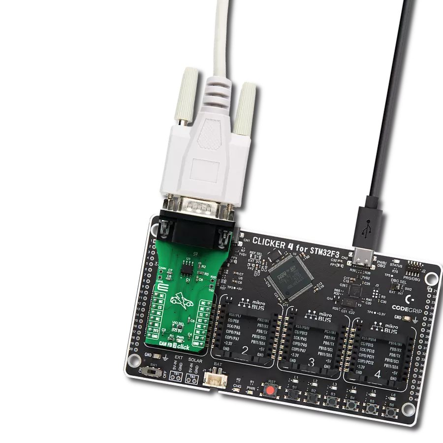
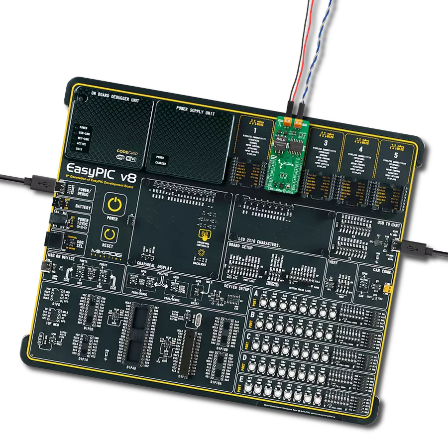
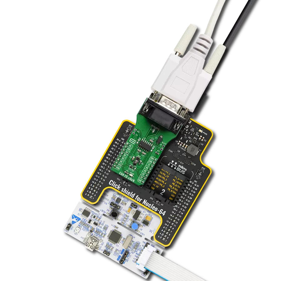
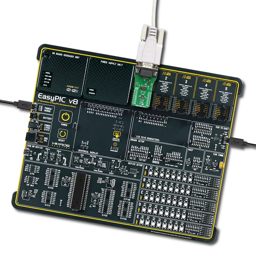
CAN FD 2 Click
Dev. board
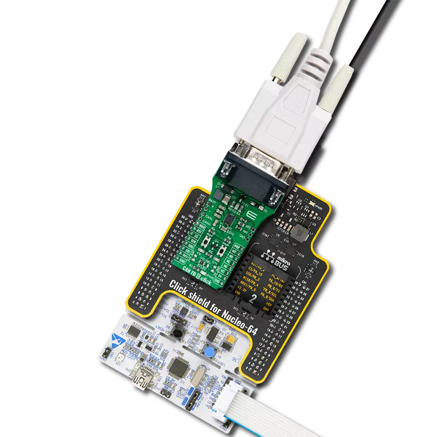
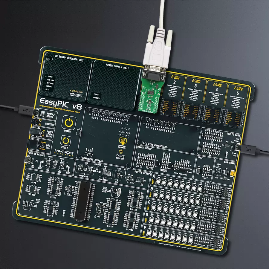
EasyPIC v8
Compiler
NECTO Studio
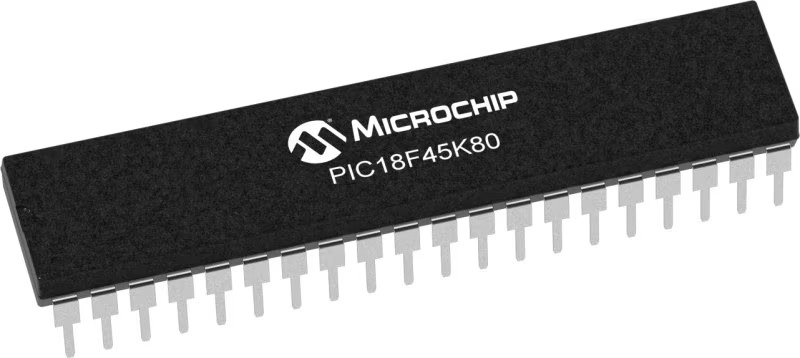
MCU
PIC18F45K80
Accelerate your automotive diagnostics with our state-of-the-art high-speed CAN FD transceiver
A
A
Hardware Overview
How does it work?
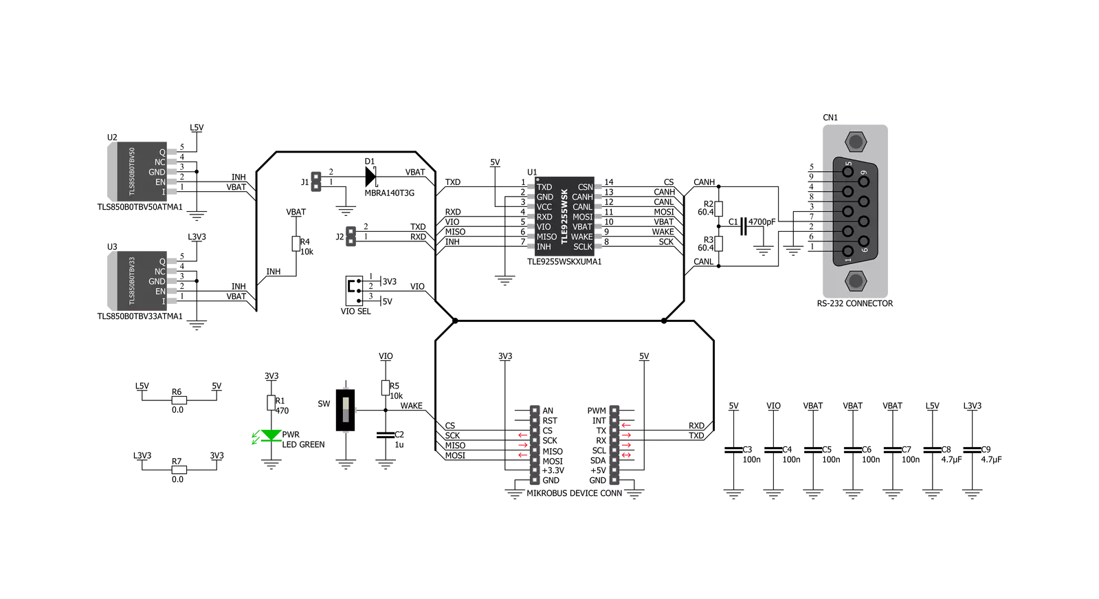
CAN FD 2 Click is based on the TLE9255W, a standard HS CAN transceiver from Infineon that provides CAN partial networking functions also a CAN FD capability of up to 5 MBit/s in HS CAN networks. Configured as a partial networking HS CAN transceiver, the TLE9255W can drive and receive CAN FD messages. It can also be used to block the payload of CAN FD messages. This CAN FD tolerant feature allows the usage of microcontrollers in CAN FD networks that are not CAN FD capable. The two non-low power modes (Normal-operating Mode and Receive-only Mode) and the two low power modes (Sleep Mode and Stand-by Mode) provide minimum current consumption based on the required functionality. The SPI of TLE9255W controls the setup of the wake-up messages and the status message generated by the internal state machine. Most functions, including wake-up functions, INH
output control, mode control, and Undervoltage control, are configurable by the SPI. This allows a very flexible usage of the TLE9255W in different applications. High-speed CAN (HS CAN) is a serial bus system that connects microcontrollers, sensors, and actuators for real-time control applications. ISO 11898-2 (2016) describes using the Controller Area Network (CAN) within road vehicles. According to the 7-layer OSI reference model, the physical layer of an HS CAN bus system specifies the data transmission from one CAN node to all other available CAN nodes within the network. The CAN transceiver is part of the physical layer. The HS CAN transceiver TLE9255W includes a receiver and a transmitter unit, allowing the transceiver to send data to the bus medium and monitor the data from the bus medium simultaneously. It converts the serial data stream, available on the transmit data input TxD, to a
differential output signal on the CAN bus provided by the CANH and CANL pins. The receiver stage of the TLE9255W monitors the data on the CAN bus and converts it to a serial, single-ended signal on the RxD output pin. Given all the features its components offer, the CAN FD 2 Click is best used for HS CAN networks in automotive applications and HS CAN networks in industrial applications. The onboard SMD jumper labeled the VIO SEL selects which voltage rail will be used as the logic voltage level. It offers voltage selection between 3.3V and 5V so that the click board™ can be interfaced with both the 3.3V and 5V capable MCUs. The two UART wires (RX and TX) can also be connected directly through two pins to UART External Pads on the board's left edge. With R6 and R7 jumpers populated allows you to use this board with a standard 12V battery connected to the Battery Pads at the right side of the board.

Features overview
Development board
EasyPIC v8 is a development board specially designed for the needs of rapid development of embedded applications. It supports many high pin count 8-bit PIC microcontrollers from Microchip, regardless of their number of pins, and a broad set of unique functions, such as the first-ever embedded debugger/programmer. The development board is well organized and designed so that the end-user has all the necessary elements, such as switches, buttons, indicators, connectors, and others, in one place. Thanks to innovative manufacturing technology, EasyPIC v8 provides a fluid and immersive working experience, allowing access anywhere and under any
circumstances at any time. Each part of the EasyPIC v8 development board contains the components necessary for the most efficient operation of the same board. In addition to the advanced integrated CODEGRIP programmer/debugger module, which offers many valuable programming/debugging options and seamless integration with the Mikroe software environment, the board also includes a clean and regulated power supply module for the development board. It can use a wide range of external power sources, including a battery, an external 12V power supply, and a power source via the USB Type-C (USB-C) connector.
Communication options such as USB-UART, USB DEVICE, and CAN are also included, including the well-established mikroBUS™ standard, two display options (graphical and character-based LCD), and several different DIP sockets. These sockets cover a wide range of 8-bit PIC MCUs, from the smallest PIC MCU devices with only eight up to forty pins. EasyPIC v8 is an integral part of the Mikroe ecosystem for rapid development. Natively supported by Mikroe software tools, it covers many aspects of prototyping and development thanks to a considerable number of different Click boards™ (over a thousand boards), the number of which is growing every day.

Microcontroller Overview
MCU Card / MCU
Architecture
PIC
MCU Memory (KB)
32
Silicon Vendor
Microchip
Pin count
40
RAM (Bytes)
3648
You complete me!
Accessories
DB9 Cable Female-to-Female (2m) cable is essential for establishing dependable serial data connections between devices. With its DB9 female connectors on both ends, this cable enables a seamless link between various equipment, such as computers, routers, switches, and other serial devices. Measuring 2 meters in length, it offers flexibility in arranging your setup without compromising data transmission quality. Crafted with precision, this cable ensures consistent and reliable data exchange, making it suitable for industrial applications, office environments, and home setups. Whether configuring networking equipment, accessing console ports, or utilizing serial peripherals, this cable's durable construction and robust connectors guarantee a stable connection. Simplify your data communication needs with the 2m DB9 female-to-female cable, an efficient solution designed to meet your serial connectivity requirements easily and efficiently.

Used MCU Pins
mikroBUS™ mapper
Take a closer look
Click board™ Schematic
Step by step
Project assembly

Start by selecting your development board and Click board™. Begin with the EasyPIC v8 as your development board.


Track your results in real time
Application Output
1. Application Output - In Debug mode, the 'Application Output' window enables real-time data monitoring, offering direct insight into execution results. Ensure proper data display by configuring the environment correctly using the provided tutorial.

2. UART Terminal - Use the UART Terminal to monitor data transmission via a USB to UART converter, allowing direct communication between the Click board™ and your development system. Configure the baud rate and other serial settings according to your project's requirements to ensure proper functionality. For step-by-step setup instructions, refer to the provided tutorial.

3. Plot Output - The Plot feature offers a powerful way to visualize real-time sensor data, enabling trend analysis, debugging, and comparison of multiple data points. To set it up correctly, follow the provided tutorial, which includes a step-by-step example of using the Plot feature to display Click board™ readings. To use the Plot feature in your code, use the function: plot(*insert_graph_name*, variable_name);. This is a general format, and it is up to the user to replace 'insert_graph_name' with the actual graph name and 'variable_name' with the parameter to be displayed.

Software Support
Library Description
This library contains API for CAN FD 2 Click driver.
Key functions:
canfd2_generic_read- Generic read functioncanfd2_write_data- Generic write the byte of data functioncanfd2_get_mode- Get operating mode function
Open Source
Code example
The complete application code and a ready-to-use project are available through the NECTO Studio Package Manager for direct installation in the NECTO Studio. The application code can also be found on the MIKROE GitHub account.
/*!
 * \file
 * \brief CanFd2 Click example
 *
 * # Description
 * This example reads and processes data from CAN FD 2 Clicks.
 *
 * The demo application is composed of two sections :
 *
 * ## Application Init
 * Initializes the driver and configures the Click board for the selected mode.
 *
 * ## Application Task
 * Depending on the selected mode, it reads all the received data or sends the desired message
 * every 2 seconds.
 *
 * ## Additional Function
 * - static void canfd2_clear_app_buf ( void )
 * - static err_t canfd2_process ( canfd2_t *ctx )
 *
 * \author MikroE Team
 *
 */
// ------------------------------------------------------------------- INCLUDES

#include "board.h"
#include "log.h"
#include "canfd2.h"
#include "string.h"

// Comment out the line below in order to switch the application mode to receiver
#define DEMO_APP_TRANSMITTER

// Text message to send in the transmitter application mode
#define DEMO_TEXT_MESSAGE           "MIKROE - CAN FD 2 Click board\r\n\0"

#define PROCESS_BUFFER_SIZE 200

static canfd2_t canfd2;
static log_t logger;

static uint8_t app_buf[ PROCESS_BUFFER_SIZE ] = { 0 };
static int32_t app_buf_len = 0;

/**
 * @brief CAN FD 2 clearing application buffer.
 * @details This function clears memory of application buffer and reset its length.
 * @note None.
 */
static void canfd2_clear_app_buf ( void );

/**
 * @brief CAN FD 2 data reading function.
 * @details This function reads data from device and concatenates data to application buffer.
 * @param[in] ctx : Click context object.
 * See #canfd2_t object definition for detailed explanation.
 * @return @li @c  0 - Read some data.
 *         @li @c -1 - Nothing is read.
 * See #err_t definition for detailed explanation.
 * @note None.
 */
static err_t canfd2_process ( canfd2_t *ctx );

// ------------------------------------------------------ APPLICATION FUNCTIONS

void application_init ( void )
{
    log_cfg_t log_cfg;
    canfd2_cfg_t cfg;

    /**
     * Logger initialization.
     * Default baud rate: 115200
     * Default log level: LOG_LEVEL_DEBUG
     * @note If USB_UART_RX and USB_UART_TX
     * are defined as HAL_PIN_NC, you will
     * need to define them manually for log to work.
     * See @b LOG_MAP_USB_UART macro definition for detailed explanation.
     */
    LOG_MAP_USB_UART( log_cfg );
    log_init( &logger, &log_cfg );
    log_info( &logger, "---- Application Init ----" );

    //  Click initialization.

    canfd2_cfg_setup( &cfg );
    CANFD2_MAP_MIKROBUS( cfg, MIKROBUS_1 );
    canfd2_init( &canfd2, &cfg );

    CANFD2_SET_DATA_SAMPLE_EDGE;
    Delay_ms ( 100 );

#ifdef DEMO_APP_TRANSMITTER
    canfd2_set_mode( &canfd2, CANFD2_OP_MODE_NORMAL );
    if ( CANFD2_OP_MODE_NORMAL == canfd2_get_mode ( &canfd2 ) )
    {
        log_info( &logger, "--- TRANSMITTER MODE ---" );
    }
    else
    {
        log_info( &logger, "--- ERROR ---" );
        log_printf( &logger, "Please restart your system.\r\n" );
        for ( ; ; );
    }
#else
    canfd2_set_mode( &canfd2, CANFD2_OP_MODE_RECEIVE_ONLY );
    if ( CANFD2_OP_MODE_RECEIVE_ONLY == canfd2_get_mode ( &canfd2 ) )
    {
        log_info( &logger, "--- RECEIVER MODE ---" );
    }
    else
    {
        log_info( &logger, "--- ERROR ---" );
        log_printf( &logger, "Please restart your system.\r\n" );
        for ( ; ; );
    }
#endif
    Delay_ms ( 100 );
}

void application_task ( void )
{
#ifdef DEMO_APP_TRANSMITTER
    canfd2_generic_write( &canfd2, DEMO_TEXT_MESSAGE, strlen ( DEMO_TEXT_MESSAGE ) );
    log_info( &logger, "--- The message is sent ---" );
    Delay_ms ( 1000 );
    Delay_ms ( 1000 );
    Delay_ms ( 1000 );
#else
    canfd2_process( &canfd2 );
    if ( app_buf_len > 0 )
    {
        Delay_ms ( 100 );
        canfd2_process ( &canfd2 );
        log_printf( &logger, "Received data: %s", app_buf );
        canfd2_clear_app_buf( );
    }
#endif
}

int main ( void )
{
    /* Do not remove this line or clock might not be set correctly. */
    #ifdef PREINIT_SUPPORTED
    preinit();
    #endif

    application_init( );

    for ( ; ; )
    {
        application_task( );
    }

    return 0;
}

static void canfd2_clear_app_buf ( void )
{
    memset( app_buf, 0, app_buf_len );
    app_buf_len = 0;
}

static err_t canfd2_process ( canfd2_t *ctx )
{
    uint8_t rx_buf[ PROCESS_BUFFER_SIZE ] = { 0 };
    int32_t rx_size = 0;
    rx_size = canfd2_generic_read( ctx, rx_buf, PROCESS_BUFFER_SIZE );
    if ( rx_size > 0 )
    {
        int32_t buf_cnt = app_buf_len;
        if ( ( ( app_buf_len + rx_size ) > PROCESS_BUFFER_SIZE ) && ( app_buf_len > 0 ) )
        {
            buf_cnt = PROCESS_BUFFER_SIZE - ( ( app_buf_len + rx_size ) - PROCESS_BUFFER_SIZE );
            memmove ( app_buf, &app_buf[ PROCESS_BUFFER_SIZE - buf_cnt ], buf_cnt );
        }
        for ( int32_t rx_cnt = 0; rx_cnt < rx_size; rx_cnt++ )
        {
            if ( rx_buf[ rx_cnt ] )
            {
                app_buf[ buf_cnt++ ] = rx_buf[ rx_cnt ];
                if ( app_buf_len < PROCESS_BUFFER_SIZE )
                {
                    app_buf_len++;
                }
            }
        }
        return CANFD2_OK;
    }
    return CANFD2_ERROR;
}

// ------------------------------------------------------------------------ END