Create innovative entertainment experiences with VZ43FC1B5640007L and PIC18LF46K80
Vibrate to your rhythm

Published Nov 01, 2023
Click board™
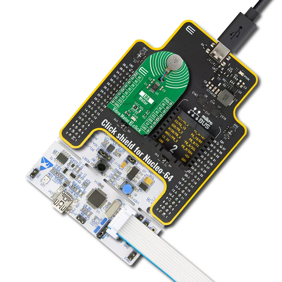
Vibro Motor 2 Click
Dev. board
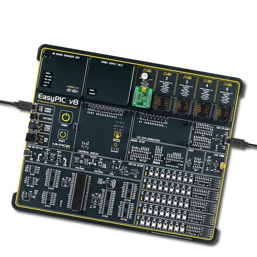
EasyPIC v8
Compiler
NECTO Studio
MCU
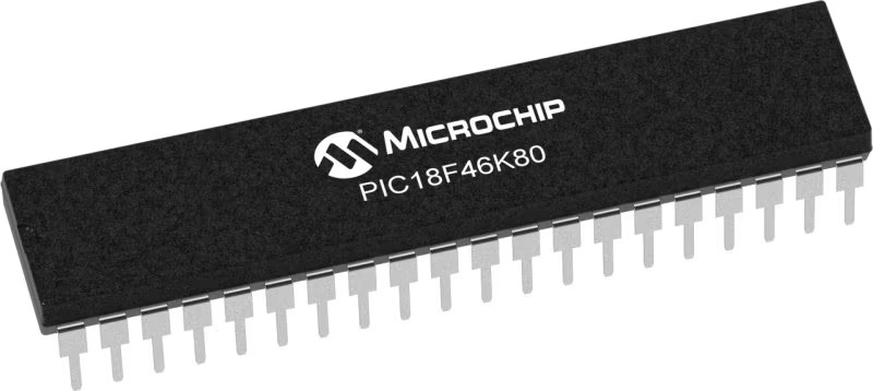
PIC18LF46K80
Elevate user interactions by incorporating controlled vibrations into your devices, providing tactile feedback that enhances user engagement
A
A
Hardware Overview
How does it work?
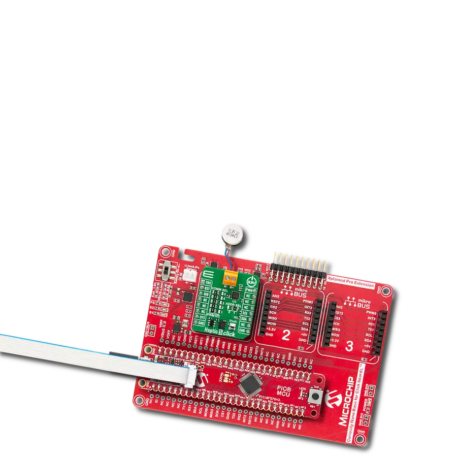
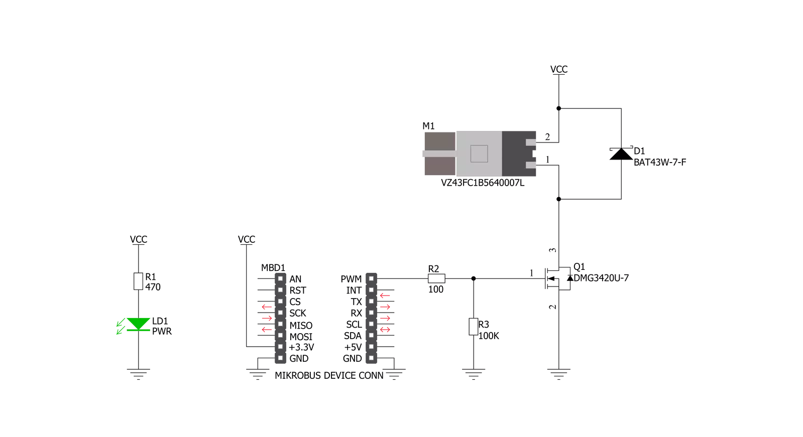
Vibro Motor 2 Click is based on the VZ43FC1B5640007L, a compact Eccentric Rotating Mass (ERM) motor that generates vibration/haptic feedback from Vybronics. This motor contains a small eccentric weight on its rotor, producing a vibration effect while rotating it. The VZ43FC1B5640007L draws a typical 100mA while creating a sizable vibration force of 0.91G and makes an excellent choice for applications requiring crisp haptic feedback and low power consumption. This Click board™ also uses the
DMG3420U N-channel MOSFET to drive the ERM motor since the MCU cannot provide enough power for the motor driving. The PWM signal drives the gate of the MOSFET, routed to the PWM pin of the mikroBUS™ socket. The PWM signal toggles the MOSFET gate with pulses of a certain width. As a result, the current through the motor is varied depending on the pulse width of the PWM signal, which directly affects the speed of the motor, effectively controlling the vibration force that way. The circuit also contains a protection
diode, which protects the transistor from the reverse voltage since the motor represents an inductive load. Turning off its current can produce a kickback voltage that can damage the transistor. This Click board™ can be operated only with a 3.3V logic voltage level. The board must perform appropriate logic voltage level conversion before using MCUs with different logic levels. Also, it comes equipped with a library containing functions and an example code that can be used as a reference for further development.


Features overview
Development board
EasyPIC v8 is a development board specially designed for the needs of rapid development of embedded applications. It supports many high pin count 8-bit PIC microcontrollers from Microchip, regardless of their number of pins, and a broad set of unique functions, such as the first-ever embedded debugger/programmer. The development board is well organized and designed so that the end-user has all the necessary elements, such as switches, buttons, indicators, connectors, and others, in one place. Thanks to innovative manufacturing technology, EasyPIC v8 provides a fluid and immersive working experience, allowing access anywhere and under any
circumstances at any time. Each part of the EasyPIC v8 development board contains the components necessary for the most efficient operation of the same board. In addition to the advanced integrated CODEGRIP programmer/debugger module, which offers many valuable programming/debugging options and seamless integration with the Mikroe software environment, the board also includes a clean and regulated power supply module for the development board. It can use a wide range of external power sources, including a battery, an external 12V power supply, and a power source via the USB Type-C (USB-C) connector.
Communication options such as USB-UART, USB DEVICE, and CAN are also included, including the well-established mikroBUS™ standard, two display options (graphical and character-based LCD), and several different DIP sockets. These sockets cover a wide range of 8-bit PIC MCUs, from the smallest PIC MCU devices with only eight up to forty pins. EasyPIC v8 is an integral part of the Mikroe ecosystem for rapid development. Natively supported by Mikroe software tools, it covers many aspects of prototyping and development thanks to a considerable number of different Click boards™ (over a thousand boards), the number of which is growing every day.

Microcontroller Overview
MCU Card / MCU
Architecture
PIC
MCU Memory (KB)
64
Silicon Vendor
Microchip
Pin count
40
RAM (Bytes)
3648
Used MCU Pins
mikroBUS™ mapper
Take a closer look
Click board™ Schematic
Step by step
Project assembly

Start by selecting your development board and Click board™. Begin with the EasyPIC v8 as your development board.


Software Support
Library Description
This library contains API for Vibro Motor 2 Click driver.
Key functions:
vibromotor2_set_duty_cycle- This function sets the PWM duty cycle in percentages ( Range[ 0..1 ] )vibromotor2_pwm_stop- This function stops the PWM moudle outputvibromotor2_pwm_start- This function starts the PWM moudle output.
Open Source
Code example
The complete application code and a ready-to-use project are available through the NECTO Studio Package Manager for direct installation in the NECTO Studio. The application code can also be found on the MIKROE GitHub account.
/*!
 * @file main.c
 * @brief VibroMotor2 Click example
 *
 * # Description
 * This application contorl the speed of vibro motor.
 *
 * The demo application is composed of two sections :
 *
 * ## Application Init
 * Initializes GPIO driver and PWM.
 * Configures PWM to 5kHz frequency, calculates maximum duty ratio and starts PWM
 * with duty ratio value 0.
 *
 * ## Application Task
 * Allows user to enter desired command to control
 * Vibro Motor Click board.
 *
 * @author Stefan Ilic
 *
 */

#include "board.h"
#include "log.h"
#include "vibromotor2.h"


static vibromotor2_t vibromotor2;
static log_t logger;

void application_init ( void ) {
    log_cfg_t log_cfg;  /**< Logger config object. */
    vibromotor2_cfg_t vibromotor2_cfg;  /**< Click config object. */

    /**
     * Logger initialization.
     * Default baud rate: 115200
     * Default log level: LOG_LEVEL_DEBUG
     * @note If USB_UART_RX and USB_UART_TX
     * are defined as HAL_PIN_NC, you will
     * need to define them manually for log to work.
     * See @b LOG_MAP_USB_UART macro definition for detailed explanation.
     */
    LOG_MAP_USB_UART( log_cfg );
    log_init( &logger, &log_cfg );
    log_info( &logger, " Application Init " );

    // Click initialization.

    vibromotor2_cfg_setup( &vibromotor2_cfg );
    VIBROMOTOR2_MAP_MIKROBUS( vibromotor2_cfg, MIKROBUS_1 );
    err_t init_flag  = vibromotor2_init( &vibromotor2, &vibromotor2_cfg );
    if ( PWM_ERROR == init_flag ) {
        log_error( &logger, " Application Init Error. " );
        log_info( &logger, " Please, run program again... " );

        for ( ; ; );
    }

    vibromotor2_set_duty_cycle ( &vibromotor2, 0.0 );
    vibromotor2_pwm_start( &vibromotor2 );

    log_info( &logger, " Application Task " );
}

void application_task ( void ) {
    static int8_t duty_cnt = 1;
    static int8_t duty_inc = 1;
    float duty = duty_cnt / 10.0;

    vibromotor2_set_duty_cycle ( &vibromotor2, duty );
    log_printf( &logger, "> Duty: %d%%\r\n", ( uint16_t )( duty_cnt * 10 ) );

    Delay_ms ( 500 );

    if ( 10 == duty_cnt ) {
        duty_inc = -1;
    } else if ( 0 == duty_cnt ) {
        duty_inc = 1;
    }
    duty_cnt += duty_inc;
}

int main ( void )
{
    /* Do not remove this line or clock might not be set correctly. */
    #ifdef PREINIT_SUPPORTED
    preinit();
    #endif

    application_init( );

    for ( ; ; )
    {
        application_task( );
    }

    return 0;
}

// ------------------------------------------------------------------------ END
Additional Support
Resources
Category:Haptic