Transform your audio experience with TDA7491 and PIC18F27K42
Unleash the full audio potential
Published Nov 01, 2023
Click board™
AudioAmp 2 Click
Dev. board
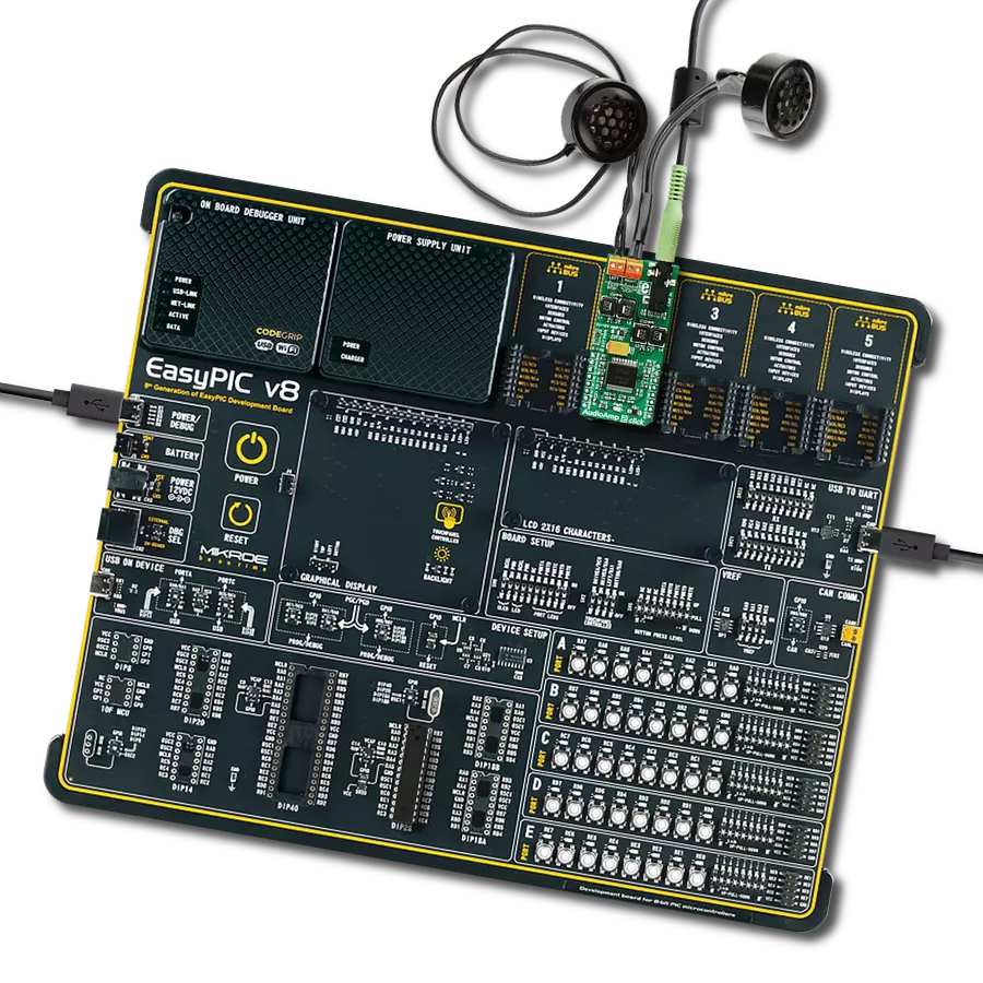
EasyPIC v8
Compiler
NECTO Studio
MCU
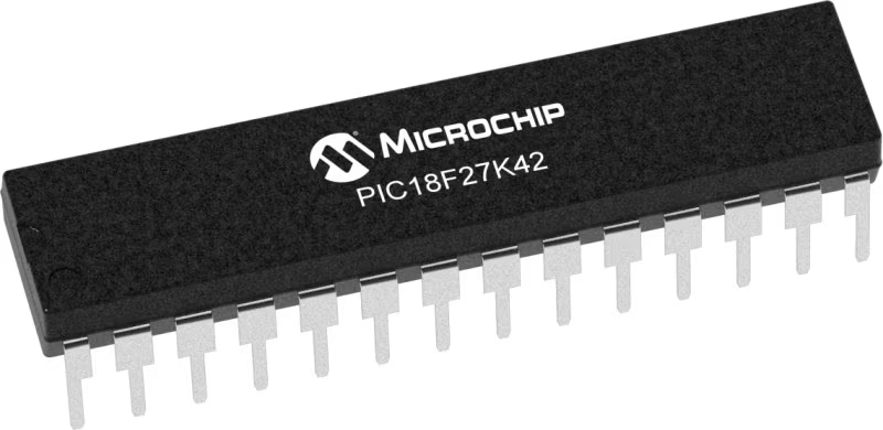
PIC18F27K42
Upgrade your embedded solution audio capabilities to a premium level with a powerful and reliable audio amplifier
A
A
Hardware Overview
How does it work?
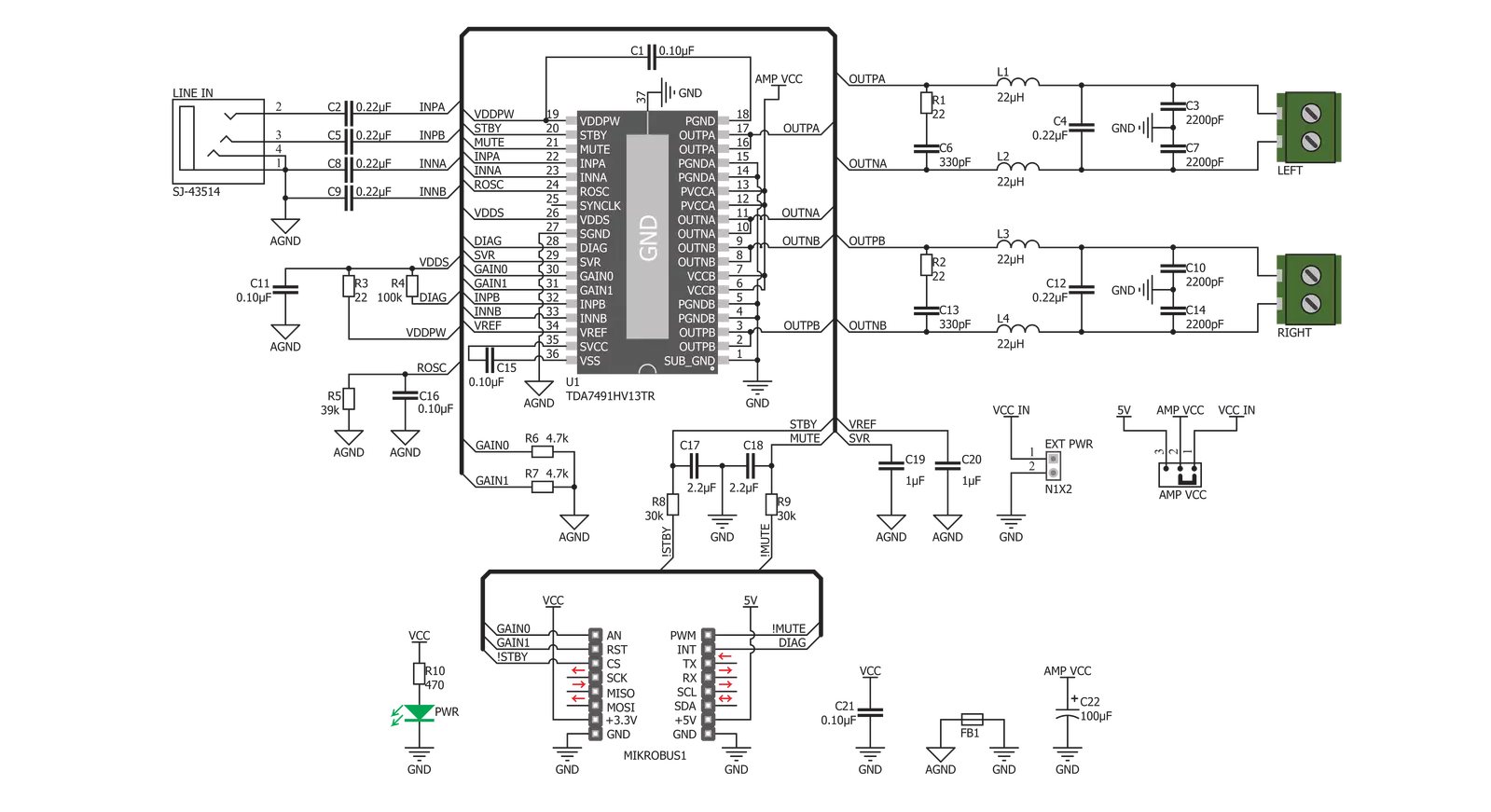
AudioAmp 2 Click is based on the TDA7491, a dual BTL class-D audio amplifier IC from STMicroelectronics capable of delivering up to 20W to 8Ω load. This IC uses the bridge-tied load (BTL) topology, which means that the output load is driven by two amplifier stages, one of them being inverted. This results in twice the voltage swing on the output or four times more power. This also means higher power dissipation, but due to the high efficiency of the TDA7491, the power dissipation is still low enough to be handled by an exposed IC pad. This amplifier offers low noise and good-quality audio amplification. The amplifier's frequency response goes from under 20Hz to above 20kHz, covering the entire audio range of the spectrum. Total Harmonic Distortion (THD) 10% at maximum output power, with the 8Ω load. However, THD decays fast as the output power reduces and the power supply voltage rises, respecting the maximum ratings of this IC. The datasheet of the TDA7491 IC offers detailed information about the technical characteristics of the amplifier IC itself. The output modulation scheme of the BTL is the unipolar pulse width modulation (PWM). The output voltage varies between 0V and +VCC for the positive output driver
and between 0V and -VCC for the negative output driver. For 0V at the input, the outputs theoretically cancel out each other, resulting in no DC component at the output. In practice, a small delay is introduced to avoid both stages switching simultaneously when the input is 0V. Using a unipolar PWM scheme simplifies The power amplifier IC has protection against the pop sounds when powering the device ON or OFF. However, standby and mute pins provide a way to reduce startup noises further. STBY pin of the IC puts the device in the Standby mode. This will turn the internal power-demanding circuitry OFF, reducing the power consumption to a minimum. MUTE pin allows the inputs to be rerouted internally to GND. Combining STBY and MUTE modes allows it to completely avoid pop sounds at the power up or shut down. STBY pin is routed to the mikroBUS™ CS pin, while the MUTE pin is routed to the mikroBUS™ PWM pin, labeled MUTE. This Click board™ allows the selection of the input gain. Input signal gain staging is important to provide an adequate input level for the amplifier IC. For example, if the input signal is too low, the amplifier might not be able to reach the required output power. Therefore, a corrective gain is applied to the input signal. This is
done by applying logic levels to two GAIN pins of the TDA7491 IC (GAIN0 and GAIN1). The GAIN0 pin is routed to the mikroBUS™ AN pin, while the GAIN1 pin is routed to the mikroBUS™ RST pin. Pins are labeled as GN0 and GN1, respectively. The DIAG pin allows monitoring of the fault conditions. When the short-circuit or thermal overload protection is activated, the DIAG pin will be set to a HIGH logic level through the onboard pull-up resistor, signaling the fault condition to the host MCU. This open drain output actively sinks current when no fault condition exists, keeping this pin in a LOW logic state. This pin is routed to the mikroBUS™ INT pin, labeled as DIA. The Click board™ is equipped with a 3.5mm stereo jack connector to connect the line-level audio input. Besides the input jack, there are also two screw terminals used for connecting the output speakers (4Ω to 8Ω). By default, the Click board™ is powered via the mikroBUS™ 5V rail. This will allow the amplifier to work with limited power. Therefore, an external header is provided, which allows the external power supply to be used with up to 18V. An SMD jumper labeled AMP VCC must be placed in the EXT position to select the external power supply.

Features overview
Development board
EasyPIC v8 is a development board specially designed for the needs of rapid development of embedded applications. It supports many high pin count 8-bit PIC microcontrollers from Microchip, regardless of their number of pins, and a broad set of unique functions, such as the first-ever embedded debugger/programmer. The development board is well organized and designed so that the end-user has all the necessary elements, such as switches, buttons, indicators, connectors, and others, in one place. Thanks to innovative manufacturing technology, EasyPIC v8 provides a fluid and immersive working experience, allowing access anywhere and under any
circumstances at any time. Each part of the EasyPIC v8 development board contains the components necessary for the most efficient operation of the same board. In addition to the advanced integrated CODEGRIP programmer/debugger module, which offers many valuable programming/debugging options and seamless integration with the Mikroe software environment, the board also includes a clean and regulated power supply module for the development board. It can use a wide range of external power sources, including a battery, an external 12V power supply, and a power source via the USB Type-C (USB-C) connector.
Communication options such as USB-UART, USB DEVICE, and CAN are also included, including the well-established mikroBUS™ standard, two display options (graphical and character-based LCD), and several different DIP sockets. These sockets cover a wide range of 8-bit PIC MCUs, from the smallest PIC MCU devices with only eight up to forty pins. EasyPIC v8 is an integral part of the Mikroe ecosystem for rapid development. Natively supported by Mikroe software tools, it covers many aspects of prototyping and development thanks to a considerable number of different Click boards™ (over a thousand boards), the number of which is growing every day.

Microcontroller Overview
MCU Card / MCU
Architecture
PIC
MCU Memory (KB)
128
Silicon Vendor
Microchip
Pin count
28
RAM (Bytes)
8192
Used MCU Pins
mikroBUS™ mapper
Take a closer look
Click board™ Schematic
Step by step
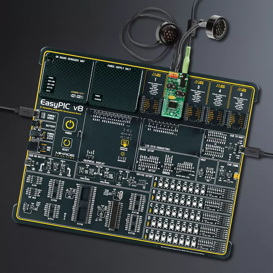
Project assembly

Start by selecting your development board and Click board™. Begin with the EasyPIC v8 as your development board.


Software Support
Library Description
This library contains API for AudioAmp 2 Click driver.
Key functions:
audioamp2_set_mode- Mode Set functionaudioamp2_set_gain- Gain Set functionaudioamp2_check_diagnostic- Diagnostic Check function
Open Source
Code example
The complete application code and a ready-to-use project are available through the NECTO Studio Package Manager for direct installation in the NECTO Studio. The application code can also be found on the MIKROE GitHub account.
/*!
 * \file
 * \brief Audio Amp 2 Click example
 *
 * # Description
 * This application amplifies the sound on the speakers.
 *
 * The demo application is composed of two sections :
 *
 * ## Application Init
 * Initializes GPIO driver and puts device in Standby Mode as default
 * operation mode and selects 20dB as default gain selection.
 *
 * ## Application Task
 * Activates Mute operation mode for 4 seconds and after that activates Play mode.
 * When the device is in Play mode then changes the gain selection, first sets the minimum gain (20dB) for 8 seconds
 * and then sets the maximum gain (32dB) for 8 seconds too.
 *
 * *note:*
 * Internally, the gain is set by changing the feedback resistors of the amplifier.
 *
 * \author MikroE Team
 *
 */
// ------------------------------------------------------------------- INCLUDES

#include "board.h"
#include "log.h"
#include "audioamp2.h"

// ------------------------------------------------------------------ VARIABLES

static audioamp2_t audioamp2;
static log_t logger;

// ------------------------------------------------------ APPLICATION FUNCTIONS

void application_init ( void )
{
    log_cfg_t log_cfg;
    audioamp2_cfg_t cfg;

    /**
     * Logger initialization.
     * Default baud rate: 115200
     * Default log level: LOG_LEVEL_DEBUG
     * @note If USB_UART_RX and USB_UART_TX
     * are defined as HAL_PIN_NC, you will
     * need to define them manually for log to work.
     * See @b LOG_MAP_USB_UART macro definition for detailed explanation.
     */
    LOG_MAP_USB_UART( log_cfg );
    log_init( &logger, &log_cfg );
    log_info(&logger, "---- Application Init ----");

    //  Click initialization.

    audioamp2_cfg_setup( &cfg );
    AUDIOAMP2_MAP_MIKROBUS( cfg, MIKROBUS_1 );
    audioamp2_init( &audioamp2, &cfg );
    Delay_ms ( 100 );

    log_printf( &logger, "AudioAmp 2 is initialized \r\n \r\n" );
    Delay_ms ( 200 );
}

void application_task ( void )
{
    audioamp2_set_mode( &audioamp2, AUDIOAMP2_MUTE_MODE );
    Delay_ms ( 1000 );
    Delay_ms ( 1000 );
    Delay_ms ( 1000 );
    Delay_ms ( 1000 );
    audioamp2_set_gain( &audioamp2, AUDIOAMP2_20DB_GAIN );
    audioamp2_set_mode( &audioamp2, AUDIOAMP2_PLAY_MODE );
    // 8 seconds delay
    Delay_ms ( 1000 );
    Delay_ms ( 1000 );
    Delay_ms ( 1000 );
    Delay_ms ( 1000 );
    Delay_ms ( 1000 );
    Delay_ms ( 1000 );
    Delay_ms ( 1000 );
    Delay_ms ( 1000 );
    audioamp2_set_gain( &audioamp2, AUDIOAMP2_32DB_GAIN );
    // 8 seconds delay
    Delay_ms ( 1000 );
    Delay_ms ( 1000 );
    Delay_ms ( 1000 );
    Delay_ms ( 1000 );
    Delay_ms ( 1000 );
    Delay_ms ( 1000 );
    Delay_ms ( 1000 );
    Delay_ms ( 1000 );
}

int main ( void )
{
    /* Do not remove this line or clock might not be set correctly. */
    #ifdef PREINIT_SUPPORTED
    preinit();
    #endif

    application_init( );

    for ( ; ; )
    {
        application_task( );
    }

    return 0;
}

// ------------------------------------------------------------------------ END


