Make BLDC motor drive as simple as possible with DRV10866 and PIC18F2585
Unleash unbridled performance
Published Nov 01, 2023
Click board™
Brushless 24 Click
Dev. board
EasyPIC v8
Compiler
NECTO Studio
MCU
PIC18F2585
Harness AI-powered precision with our next-gen brushless motor control solution
A
A
Hardware Overview
How does it work?
Brushless 24 Click is based on the DRV10866, a fully integrated three-phase BLDC motor driver from Texas Instruments. The DRV10866 motor driver comes with integrated power MOSFETs with current drive capability up to 800mA peak (based on populated 3.9k resistor), specifically designed for low-noise energy-saving fan motor drive applications connected to the terminals labeled as U, V, W, and COM. It provides PWM/enable control interface (PWM pin of the mikroBUS™ socket), wide operating voltage range, robust on-chip protection features, low RDSON, and efficient switching algorithms to ensure excellent thermal performance and high drive capability. The DRV10866 implements a 150° commutation (sensorless BEMF control scheme) for
a 3-phase motor alongside a synchronous rectification mode of operation that achieves increased efficiency for motor driver applications. In addition, the DRV10866 has a frequency generator pin (FG) that outputs a 50% duty cycle of PWM waveform in the normal operation condition. The FG represents the motor speed and phase information, detectable through an interrupt pin of the mikroBUS™ socket and a blue LED indicator marked as FG. During the Start-Up sequence, the FG output will stay at high impedance until the motor speed reaches a certain level and BEMF is detected, while during lock protection conditions, the FG will remain high until the motor restarts and the Start-Up process is completed. Apart from this function, the
DRV10866 can also output either full FG or half of the FG to indicate motor status with open-drain output through the FGS SEL selection jumper. When FGS SEL is placed in a VCC position, the FG output frequency is half that when the jumper is set to a GND position. The DRV10866 has multiple built-in protection blocks, including UVLO, overcurrent protection, lock protection, and thermal shutdown protection. This Click board™ can operate with either 3.3V or 5V logic voltage levels selected via the VCC SEL jumper. This way, both 3.3V and 5V capable MCUs can use the communication lines properly. This Click board™ comes equipped with a library containing easy-to-use functions and an example code that can be used, as a reference, for further development.

Features overview
Development board
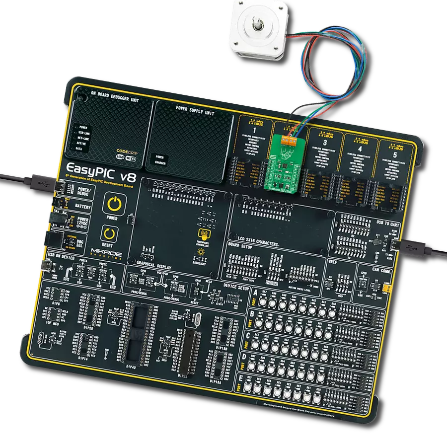
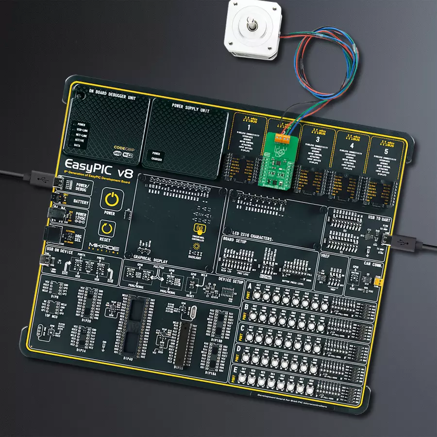
EasyPIC v8 is a development board specially designed for the needs of rapid development of embedded applications. It supports many high pin count 8-bit PIC microcontrollers from Microchip, regardless of their number of pins, and a broad set of unique functions, such as the first-ever embedded debugger/programmer. The development board is well organized and designed so that the end-user has all the necessary elements, such as switches, buttons, indicators, connectors, and others, in one place. Thanks to innovative manufacturing technology, EasyPIC v8 provides a fluid and immersive working experience, allowing access anywhere and under any
circumstances at any time. Each part of the EasyPIC v8 development board contains the components necessary for the most efficient operation of the same board. In addition to the advanced integrated CODEGRIP programmer/debugger module, which offers many valuable programming/debugging options and seamless integration with the Mikroe software environment, the board also includes a clean and regulated power supply module for the development board. It can use a wide range of external power sources, including a battery, an external 12V power supply, and a power source via the USB Type-C (USB-C) connector.
Communication options such as USB-UART, USB DEVICE, and CAN are also included, including the well-established mikroBUS™ standard, two display options (graphical and character-based LCD), and several different DIP sockets. These sockets cover a wide range of 8-bit PIC MCUs, from the smallest PIC MCU devices with only eight up to forty pins. EasyPIC v8 is an integral part of the Mikroe ecosystem for rapid development. Natively supported by Mikroe software tools, it covers many aspects of prototyping and development thanks to a considerable number of different Click boards™ (over a thousand boards), the number of which is growing every day.

Microcontroller Overview
MCU Card / MCU
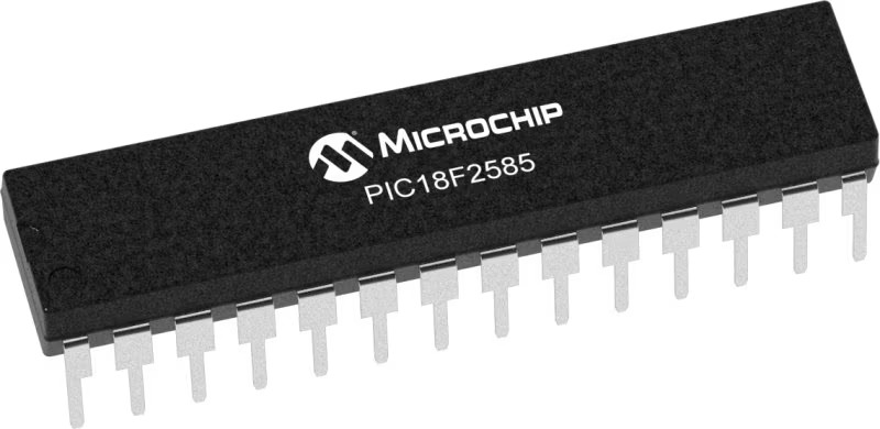
Architecture
PIC
MCU Memory (KB)
48
Silicon Vendor
Microchip
Pin count
28
RAM (Bytes)
3328
You complete me!
Accessories
Brushless DC (BLDC) Motor with a Hall sensor represents a high-performance motor from the 42BLF motor series. This motor, wired in a star configuration, boasts a Hall Effect angle of 120°, ensuring precise and reliable performance. With a compact motor length of 47mm and a lightweight design tipping the scales at just 0.29kg, this BLDC motor is engineered to meet your needs. Operating flawlessly at a voltage rating of 24VDC and a speed range of 4000 ± 10% RPM, this motor offers consistent and dependable power. It excels in a normal operational temperature range from -20 to +50°C, maintaining efficiency with a rated current of 1.9A. Also, this product seamlessly integrates with all Brushless Click boards™ and those that require BLDC motors with Hall sensors.

Used MCU Pins
mikroBUS™ mapper
Take a closer look
Click board™ Schematic

Step by step
Project assembly

Start by selecting your development board and Click board™. Begin with the EasyPIC v8 as your development board.


Track your results in real time
Application Output
1. Application Output - In Debug mode, the 'Application Output' window enables real-time data monitoring, offering direct insight into execution results. Ensure proper data display by configuring the environment correctly using the provided tutorial.

2. UART Terminal - Use the UART Terminal to monitor data transmission via a USB to UART converter, allowing direct communication between the Click board™ and your development system. Configure the baud rate and other serial settings according to your project's requirements to ensure proper functionality. For step-by-step setup instructions, refer to the provided tutorial.

3. Plot Output - The Plot feature offers a powerful way to visualize real-time sensor data, enabling trend analysis, debugging, and comparison of multiple data points. To set it up correctly, follow the provided tutorial, which includes a step-by-step example of using the Plot feature to display Click board™ readings. To use the Plot feature in your code, use the function: plot(*insert_graph_name*, variable_name);. This is a general format, and it is up to the user to replace 'insert_graph_name' with the actual graph name and 'variable_name' with the parameter to be displayed.

Software Support
Library Description
This library contains API for Brushless 24 Click driver.
Key functions:
brushless24_set_duty_cycle- Brushless 24 sets PWM duty cyclebrushless24_pwm_start- Brushless 24 start PWM modulebrushless24_get_int_state- Brushless 24 get INT pin state
Open Source
Code example
The complete application code and a ready-to-use project are available through the NECTO Studio Package Manager for direct installation in the NECTO Studio. The application code can also be found on the MIKROE GitHub account.
/*!
 * @file main.c
 * @brief Brushless 24 Click example
 *
 * # Description
 * This application is a schowcase of controlling speed of brushless motor using Brushless 24 Click.
 *
 * The demo application is composed of two sections :
 *
 * ## Application Init
 * Initialization of LOG, PWM module and additional pins.
 *
 * ## Application Task
 * In a span of second changes duty cycle from 0 to 100% which is changing speed of the motor.
 *
 * @author Stefan Ilic
 *
 */

#include "board.h"
#include "log.h"
#include "brushless24.h"

static brushless24_t brushless24;
static log_t logger;

void application_init ( void )
{
    log_cfg_t log_cfg;  /**< Logger config object. */
    brushless24_cfg_t brushless24_cfg;  /**< Click config object. */

    /**
     * Logger initialization.
     * Default baud rate: 115200
     * Default log level: LOG_LEVEL_DEBUG
     * @note If USB_UART_RX and USB_UART_TX
     * are defined as HAL_PIN_NC, you will
     * need to define them manually for log to work.
     * See @b LOG_MAP_USB_UART macro definition for detailed explanation.
     */
    LOG_MAP_USB_UART( log_cfg );
    log_init( &logger, &log_cfg );
    log_info( &logger, " Application Init " );

    // Click initialization.
    brushless24_cfg_setup( &brushless24_cfg );
    BRUSHLESS24_MAP_MIKROBUS( brushless24_cfg, MIKROBUS_1 );
    if ( PWM_ERROR == brushless24_init( &brushless24, &brushless24_cfg ) )
    {
        log_error( &logger, " Communication init." );
        for ( ; ; );
    }

    if ( BRUSHLESS24_ERROR == brushless24_default_cfg ( &brushless24 ) )
    {
        log_error( &logger, " Default configuration." );
        for ( ; ; );
    }

    log_info( &logger, " Application Task " );
}

void application_task ( void )
{
    static int8_t duty_cnt = 1;
    static int8_t duty_inc = 1;
    float duty = duty_cnt / 10.0;

    brushless24_set_duty_cycle ( &brushless24, duty );
    log_printf( &logger, "> Duty: %d%%\r\n", ( uint16_t )( duty_cnt * 10 ) );

    Delay_ms ( 1000 );

    if ( 10 == duty_cnt )
    {
        duty_inc = -1;
    }
    else if ( 0 == duty_cnt )
    {
        duty_inc = 1;
    }
    duty_cnt += duty_inc;
}

int main ( void )
{
    /* Do not remove this line or clock might not be set correctly. */
    #ifdef PREINIT_SUPPORTED
    preinit();
    #endif

    application_init( );

    for ( ; ; )
    {
        application_task( );
    }

    return 0;
}

// ------------------------------------------------------------------------ END


