Revolutionize your DC motor control with TB67H450AFNG and PIC18F26K42
Effortless control for powerful motors
Published Nov 01, 2023
Click board™
DC Motor 14 Click
Dev. board
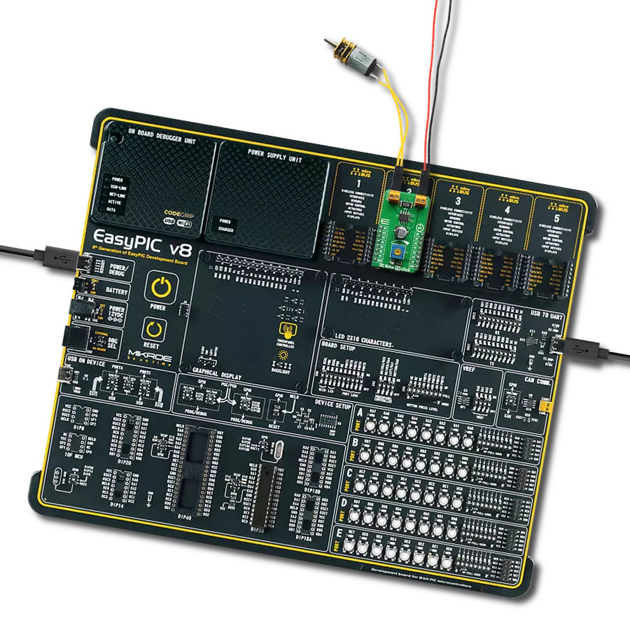
EasyPIC v8
Compiler
NECTO Studio
MCU
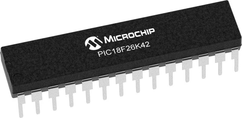
PIC18F26K42
Embrace the versatility of brushed motor control, offering four dynamic operational modes: forward, reverse, short brake, and full stop!
A
A
Hardware Overview
How does it work?
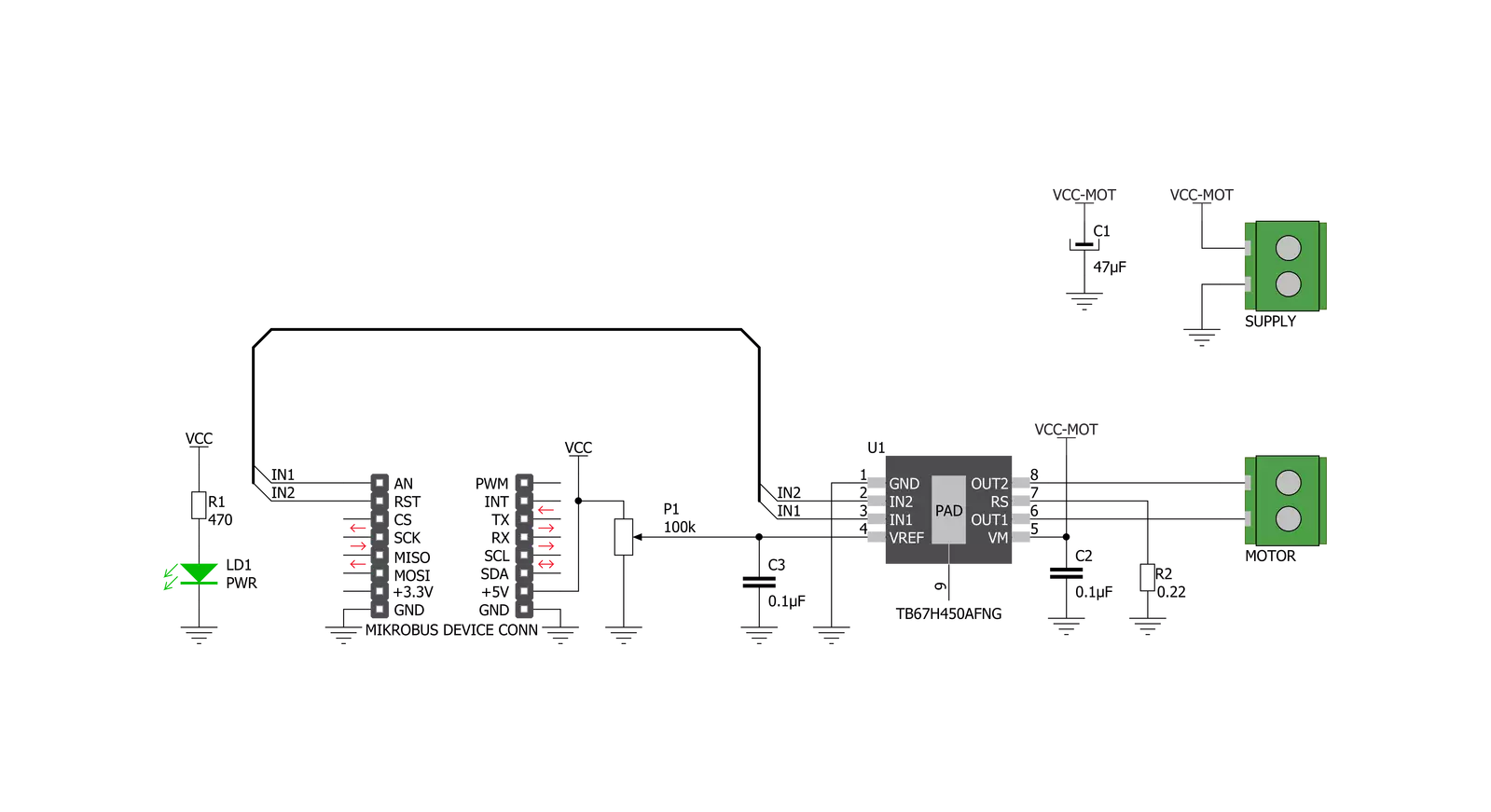
DC MOTOR 14 Click is based on the TB67H450AFNG, a PWM chopper-type brushed DC motor driver from Toshiba Semiconductor. This IC uses a proprietary BiCD manufacturing process, allowing this IC to be powered by a wide range of supply voltages, from 4.5 up to 44V. Due to the very low ON resistance of the MOSFETs, it can deliver up to 3.5A of current to the connected load. However, many external parameters affect both the maximum voltage and the current specifications, especially when the connected load is complex, such as the DC motor. In using TB67H450AFNG, the voltage should be applied to the pins of VM and VREF. The absolute maximum rating of VM supply voltage is 50V (no active). The usage range is 4.5 to 44V. The absolute maximum rating of VREF supply voltage is 5V. The usage range is 0 to 4V. There are no special procedures for inputting a power supply and shutdown feature because the TB67H450AFNG incorporates the under voltage lockout (UVLO). However, setting the motor operation to OFF is recommended under the unstable state of inputting the power supply (VM) and shutdown (transient area). After the power supply is stable, the motor should be operated by switching the input signal. The absolute maximum rating of motor output current is 3.5A. Its operating range is 3A or less. The maximum current of the actual usage is limited depending on the usage conditions (the ambient temperature, the wiring pattern of the board, the radiation path, and the exciting design).
Configure the most appropriate current value after calculating the heat and evaluating the board under the operating environment. When the logic signal is input under the condition that the voltage of the VM is not supplied, the electromotive force by an input signal is not generated. The speed of the motor can be controlled by Inputting the PWM signal to pins IN1 and IN2 and operating them with PWM control. When both IN1 and IN2 pins are set to L for 1 ms (typ.) or more, the operation mode enters the Standby mode. When IN1 or IN2 is set to H, the mode returns from the standby mode and enters the operation mode. When the constant current function is disabled, the RS pin should be connected to GND, and a voltage of 1 to 5V should be applied to the VREF pin. Maximum 30μs are required for the return time from the standby release. The OUT1 and OUT2 outputs operate after 30 μs (max) from the standby release. In this product, the current detection resistor sets a constant current threshold between RS and GND and VREF input voltage. When the constant current function is disabled, the RS pin should be connected to GND, and a voltage of 1 to 5V should be applied to the VREF pin. The constant current control is performed in Mixed Decay mode when the output current reaches the threshold due to forward and reverse rotation. In the case of the constant current control, the OFF time (toff) is fixed to 25 μs (typ.) to determine the pulse width of the current (current pulsating flow).
The percentage of Mixed Decay Mode is as follows; Fast Mode: 50% to Slow Mode: 50%. If the output current is zero-detected in Fast Mode, the outputs are in High impedance. When the junction temperature of the IC reaches the specified value, the internal detection circuit (TSD) operates to turn off the output block. It has a dead band time to prevent the IC from malfunctioning, caused by switching, and so on. Since the temperature has a hysteresis range when the junction temperature falls to the return temperature, the operation returns automatically to the normal operation. The TSD is triggered when the device is overheated irregularly. Make sure not to use the TSD function aggressively. When the IC detects an overcurrent, the internal circuit turns off the output block. It has a dead band time to avoid ISD misdetection, which may be triggered by external noise. The undervoltage detection circuit operates when the applied voltage of the VM pin falls 3.8V (typ.) or less. All output power transistors are turned off. The UVLO operation is released when the voltage applied to the VM pin rises 4.0V (typ.) or more. Although the TB67H450AFNG IC requires an external PSU, this Click board™ can operate with 5V MCUs only. The current detection resistor (R2) installed on click is 0.51 Ohm, set for a range from 0 to 1.5A. In the case of a range from 1.5 to 3A, that can be achieved by replacing it with a 0.22 Ohm resistor.

Features overview
Development board
EasyPIC v8 is a development board specially designed for the needs of rapid development of embedded applications. It supports many high pin count 8-bit PIC microcontrollers from Microchip, regardless of their number of pins, and a broad set of unique functions, such as the first-ever embedded debugger/programmer. The development board is well organized and designed so that the end-user has all the necessary elements, such as switches, buttons, indicators, connectors, and others, in one place. Thanks to innovative manufacturing technology, EasyPIC v8 provides a fluid and immersive working experience, allowing access anywhere and under any
circumstances at any time. Each part of the EasyPIC v8 development board contains the components necessary for the most efficient operation of the same board. In addition to the advanced integrated CODEGRIP programmer/debugger module, which offers many valuable programming/debugging options and seamless integration with the Mikroe software environment, the board also includes a clean and regulated power supply module for the development board. It can use a wide range of external power sources, including a battery, an external 12V power supply, and a power source via the USB Type-C (USB-C) connector.
Communication options such as USB-UART, USB DEVICE, and CAN are also included, including the well-established mikroBUS™ standard, two display options (graphical and character-based LCD), and several different DIP sockets. These sockets cover a wide range of 8-bit PIC MCUs, from the smallest PIC MCU devices with only eight up to forty pins. EasyPIC v8 is an integral part of the Mikroe ecosystem for rapid development. Natively supported by Mikroe software tools, it covers many aspects of prototyping and development thanks to a considerable number of different Click boards™ (over a thousand boards), the number of which is growing every day.

Microcontroller Overview
MCU Card / MCU
Architecture
PIC
MCU Memory (KB)
64
Silicon Vendor
Microchip
Pin count
28
RAM (Bytes)
4096
You complete me!
Accessories
DC Gear Motor - 430RPM (3-6V) represents an all-in-one combination of a motor and gearbox, where the addition of gear leads to a reduction of motor speed while increasing the torque output. This gear motor has a spur gearbox, making it a highly reliable solution for applications with lower torque and speed requirements. The most critical parameters for gear motors are speed, torque, and efficiency, which are, in this case, 520RPM with no load and 430RPM at maximum efficiency, alongside a current of 60mA and a torque of 50g.cm. Rated for a 3-6V operational voltage range and clockwise/counterclockwise rotation direction, this motor represents an excellent solution for many functions initially performed by brushed DC motors in robotics, medical equipment, electric door locks, and much more.

Used MCU Pins
mikroBUS™ mapper
Take a closer look
Click board™ Schematic
Step by step
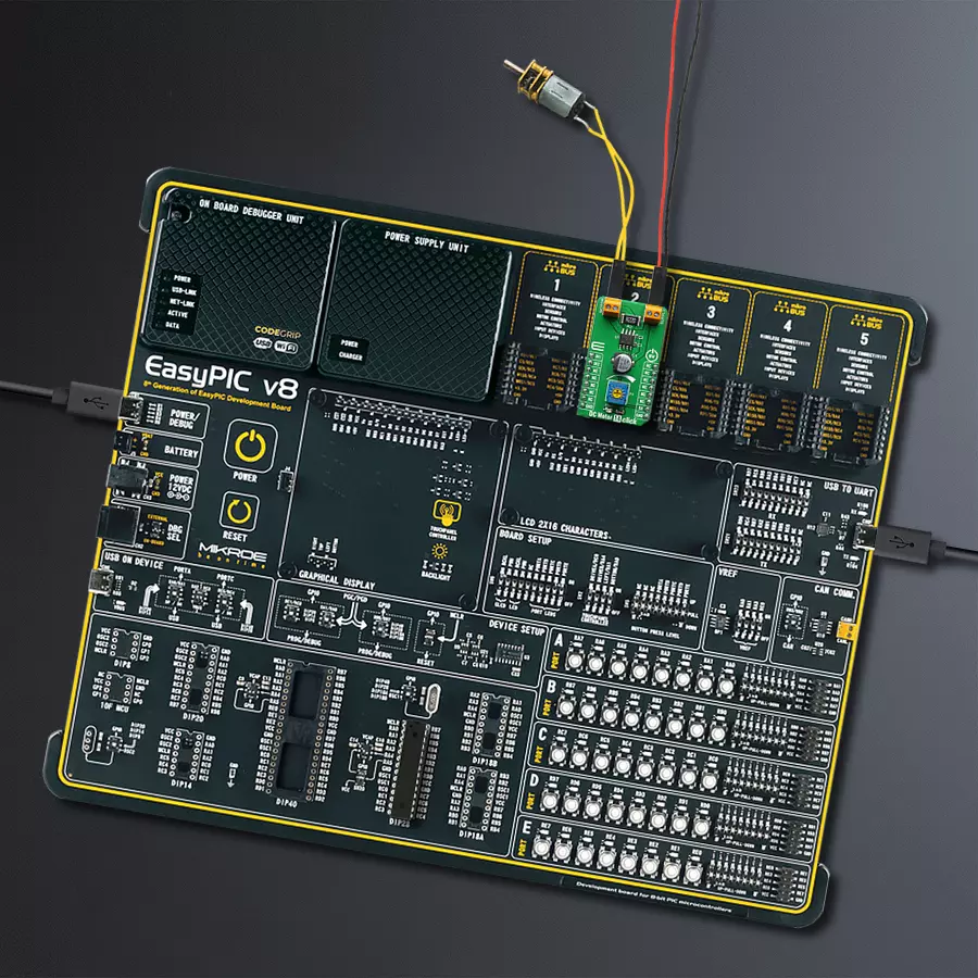
Project assembly

Start by selecting your development board and Click board™. Begin with the EasyPIC v8 as your development board.


Track your results in real time
Application Output
1. Application Output - In Debug mode, the 'Application Output' window enables real-time data monitoring, offering direct insight into execution results. Ensure proper data display by configuring the environment correctly using the provided tutorial.

2. UART Terminal - Use the UART Terminal to monitor data transmission via a USB to UART converter, allowing direct communication between the Click board™ and your development system. Configure the baud rate and other serial settings according to your project's requirements to ensure proper functionality. For step-by-step setup instructions, refer to the provided tutorial.

3. Plot Output - The Plot feature offers a powerful way to visualize real-time sensor data, enabling trend analysis, debugging, and comparison of multiple data points. To set it up correctly, follow the provided tutorial, which includes a step-by-step example of using the Plot feature to display Click board™ readings. To use the Plot feature in your code, use the function: plot(*insert_graph_name*, variable_name);. This is a general format, and it is up to the user to replace 'insert_graph_name' with the actual graph name and 'variable_name' with the parameter to be displayed.

Software Support
Library Description
This library contains API for DC Motor 14 Click driver.
Key functions:
void dcmotor14_forward ( );- Function is used to drive the motor forward.void dcmotor14_reverse ( );- Function is used to drive the motor reverse.void dcmotor14_brake ( );- Function is used to brake the motor.
Open Source
Code example
The complete application code and a ready-to-use project are available through the NECTO Studio Package Manager for direct installation in the NECTO Studio. The application code can also be found on the MIKROE GitHub account.
/*!
 * \file
 * \brief DC MOTOR 14 Click example
 *
 * # Description
 * This example demonstrates the use of DC Motor 14 Click board.
 *
 * The demo application is composed of two sections :
 *
 * ## Application Init
 * Initializes the driver and makes an initial log.
 *
 * ## Application Task
 * Drives the motor in the forward direction for 5 seconds, then pulls brake for 2 seconds,
 * and after that drives it in the reverse direction for 5 seconds, and finally,
 * disconnects the motor for 2 seconds. Each step will be logged on the USB UART where
 * you can track the program flow.
 *
 * \author MikroE Team
 *
 */
// ------------------------------------------------------------------- INCLUDES

#include "board.h"
#include "log.h"
#include "dcmotor14.h"

// ------------------------------------------------------------------ VARIABLES

static dcmotor14_t dcmotor14;
static log_t logger;

// ------------------------------------------------------ APPLICATION FUNCTIONS

void application_init ( void )
{
    log_cfg_t log_cfg;
    dcmotor14_cfg_t cfg;

    /**
     * Logger initialization.
     * Default baud rate: 115200
     * Default log level: LOG_LEVEL_DEBUG
     * @note If USB_UART_RX and USB_UART_TX
     * are defined as HAL_PIN_NC, you will
     * need to define them manually for log to work.
     * See @b LOG_MAP_USB_UART macro definition for detailed explanation.
     */
    LOG_MAP_USB_UART( log_cfg );
    log_init( &logger, &log_cfg );
    log_info(&logger, "---- Application Init ----");

    //  Click initialization.

    dcmotor14_cfg_setup( &cfg );
    DCMOTOR14_MAP_MIKROBUS( cfg, MIKROBUS_1 );
    dcmotor14_init( &dcmotor14, &cfg );
}

void application_task ( void )
{
    log_printf( &logger, "The motor turns forward! \r\n" );
    dcmotor14_forward( &dcmotor14 );
    Delay_ms ( 1000 );
    Delay_ms ( 1000 );
    Delay_ms ( 1000 );
    Delay_ms ( 1000 );
    Delay_ms ( 1000 );
    log_printf( &logger, "Pull brake! \r\n" );
    dcmotor14_brake( &dcmotor14 );
    Delay_ms ( 1000 );
    Delay_ms ( 1000 );
    log_printf( &logger, "The motor turns in reverse! \r\n" );
    dcmotor14_reverse( &dcmotor14 );
    Delay_ms ( 1000 );
    Delay_ms ( 1000 );
    Delay_ms ( 1000 );
    Delay_ms ( 1000 );
    Delay_ms ( 1000 );
    log_printf( &logger, "The motor is disconnected (High-Z)!  \r\n" );
    dcmotor14_stop( &dcmotor14 );
    Delay_ms ( 1000 );
    Delay_ms ( 1000 );
}

int main ( void )
{
    /* Do not remove this line or clock might not be set correctly. */
    #ifdef PREINIT_SUPPORTED
    preinit();
    #endif

    application_init( );

    for ( ; ; )
    {
        application_task( );
    }

    return 0;
}

// ------------------------------------------------------------------------ END


