Step into the future of BDC control with DRV8701 and PIC18LF27K40
Smooth control, maximum potential
Published Nov 01, 2023
Click board™
DC MOTOR 5 Click
Dev. board
EasyPIC v8
Compiler
NECTO Studio
MCU
PIC18LF27K40
Elevate your engineering prowess with tailor-made motor control through our cutting-edge "H-Bridge" drive solution. Take the first step towards unmatched performance and efficiency by incorporating this customizable innovation into your project today.
A
A
Hardware Overview
How does it work?
DC Motor 5 Click is based on the DRV8701 brushed DC motor gate driver from Texas Instruments. The Click is designed to run on an external power supply. It communicates with the target MCU over the following pins on the mikroBUS™ line: AN, RST, CS, PWM, and INT. The DRV8701 is an
H-bridge gate driver (a pre-driver or controller). The device integrates FET gate drivers to control four external NMOS FETs. The device can be powered with a supply voltage between 5.9V and 45V. Internal protection functions are provided: under-voltage lockout, charge pump faults,
overcurrent shutdown, short-circuit protection, pre-driver faults, and overtemperature. The motor's velocity and direction can be adjusted with two PWM input signals.

Features overview
Development board
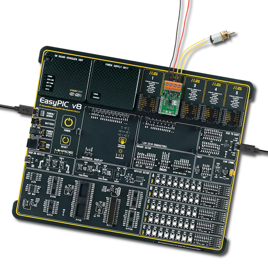
EasyPIC v8 is a development board specially designed for the needs of rapid development of embedded applications. It supports many high pin count 8-bit PIC microcontrollers from Microchip, regardless of their number of pins, and a broad set of unique functions, such as the first-ever embedded debugger/programmer. The development board is well organized and designed so that the end-user has all the necessary elements, such as switches, buttons, indicators, connectors, and others, in one place. Thanks to innovative manufacturing technology, EasyPIC v8 provides a fluid and immersive working experience, allowing access anywhere and under any
circumstances at any time. Each part of the EasyPIC v8 development board contains the components necessary for the most efficient operation of the same board. In addition to the advanced integrated CODEGRIP programmer/debugger module, which offers many valuable programming/debugging options and seamless integration with the Mikroe software environment, the board also includes a clean and regulated power supply module for the development board. It can use a wide range of external power sources, including a battery, an external 12V power supply, and a power source via the USB Type-C (USB-C) connector.
Communication options such as USB-UART, USB DEVICE, and CAN are also included, including the well-established mikroBUS™ standard, two display options (graphical and character-based LCD), and several different DIP sockets. These sockets cover a wide range of 8-bit PIC MCUs, from the smallest PIC MCU devices with only eight up to forty pins. EasyPIC v8 is an integral part of the Mikroe ecosystem for rapid development. Natively supported by Mikroe software tools, it covers many aspects of prototyping and development thanks to a considerable number of different Click boards™ (over a thousand boards), the number of which is growing every day.

Microcontroller Overview
MCU Card / MCU
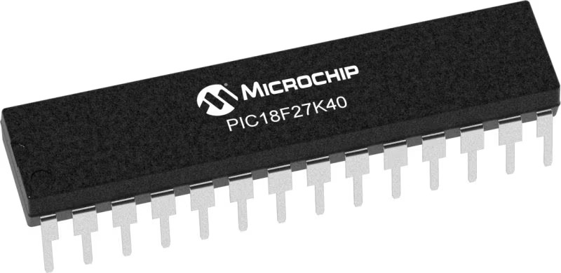
Architecture
PIC
MCU Memory (KB)
128
Silicon Vendor
Microchip
Pin count
28
RAM (Bytes)
3728
You complete me!
Accessories
DC Gear Motor - 430RPM (3-6V) represents an all-in-one combination of a motor and gearbox, where the addition of gear leads to a reduction of motor speed while increasing the torque output. This gear motor has a spur gearbox, making it a highly reliable solution for applications with lower torque and speed requirements. The most critical parameters for gear motors are speed, torque, and efficiency, which are, in this case, 520RPM with no load and 430RPM at maximum efficiency, alongside a current of 60mA and a torque of 50g.cm. Rated for a 3-6V operational voltage range and clockwise/counterclockwise rotation direction, this motor represents an excellent solution for many functions initially performed by brushed DC motors in robotics, medical equipment, electric door locks, and much more.

Used MCU Pins
mikroBUS™ mapper
Take a closer look
Click board™ Schematic

Step by step
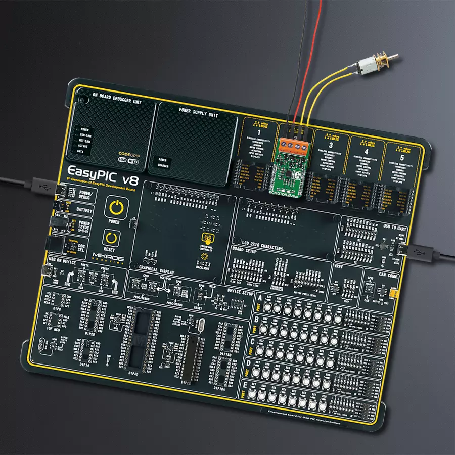
Project assembly

Start by selecting your development board and Click board™. Begin with the EasyPIC v8 as your development board.


Software Support
Library Description
This library contains API for DC Motor 5 Click driver.
Key functions:
dcmotor5_short_brake- Function brakes the engine by setting IN1 ( PWM ) and IN2 ( INT ) pins on DC Motor 5 Clickdcmotor5_stop- Function stops the engine by clearing IN1 ( PWM ) and IN2 ( INT ) pins on DC Motor 5 Clickdcmotor5_enable- Function disables the engine by clearing SLEEP ( RST ) pin on DC Motor 5 Click
Open Source
Code example
The complete application code and a ready-to-use project are available through the NECTO Studio Package Manager for direct installation in the NECTO Studio. The application code can also be found on the MIKROE GitHub account.
/*!
 * @file main.c
 * @brief DCMotor5 Click example
 *
 * # Description
 * This library contains API for the DC Motor 5 Click driver.
 * This application enables usage of brushed DC motor 5 gate driver.
 *
 * The demo application is composed of two sections :
 *
 * ## Application Init
 * Initializes GPIO, PWM and logger and enables the Click board.
 *
 * ## Application Task
 * This is a example which demonstrates the use of DC Motor 5 Click board.
 * DC Motor 5 Click controls DC Motor speed via PWM interface.
 * It shows moving in the both directions from slow to fast speed
 * and from fast to slow speed.
 * Results are being sent to the Usart Terminal where you can track their changes.
 *
 * @author Nikola Peric
 *
 */

#include "board.h"
#include "log.h"
#include "dcmotor5.h"

// ------------------------------------------------------------------ VARIABLES

static dcmotor5_t dcmotor5;
static log_t logger;
uint8_t dcmotor_direction = 1;

// ------------------------------------------------------ APPLICATION FUNCTIONS

void application_init ( void )
{
    log_cfg_t log_cfg;
    dcmotor5_cfg_t cfg;

    /**
     * Logger initialization.
     * Default baud rate: 115200
     * Default log level: LOG_LEVEL_DEBUG
     * @note If USB_UART_RX and USB_UART_TX
     * are defined as HAL_PIN_NC, you will
     * need to define them manually for log to work.
     * See @b LOG_MAP_USB_UART macro definition for detailed explanation.
     */
    LOG_MAP_USB_UART( log_cfg );
    log_init( &logger, &log_cfg );
    log_info( &logger, "---- Application Init ----" );

    //  Click initialization.

    dcmotor5_cfg_setup( &cfg );
    DCMOTOR5_MAP_MIKROBUS( cfg, MIKROBUS_1 );
    dcmotor5_init( &dcmotor5, &cfg );

    log_printf( &logger, " Initialization  PWM \r\n" );

    dcmotor5_pwm_start( &dcmotor5 );
    dcmotor5_enable ( &dcmotor5 );
    Delay_ms ( 500 );
    log_printf( &logger, "---------------------\r\n" );
    log_info( &logger, "---- Application Task ----" );
}


void application_task ( )
{
    static float duty;
    static uint8_t n_cnt;


    dcmotor5_clockwise ( &dcmotor5 );
    log_printf( &logger, "\r\n> CLOCKWISE <\r\n" );
    dcmotor5_enable ( &dcmotor5 );

    for ( n_cnt = 10; n_cnt > 0; n_cnt--  )
    {
        duty = ( float ) n_cnt ;
        duty /= 10;
        log_printf( &logger, " >" );
        dcmotor5_set_duty_cycle( &dcmotor5, duty );
        Delay_ms ( 500 );
    }
    for ( n_cnt = 1; n_cnt <= 10; n_cnt++ )
    {
        duty = ( float ) n_cnt ;
        duty /= 10;
        log_printf( &logger, " <" );
        dcmotor5_set_duty_cycle( &dcmotor5,  duty );
        Delay_ms ( 500 );
    }

    log_printf( &logger, "\r\n * Pull break *\r\n" );
    dcmotor5_short_brake( &dcmotor5 );
    Delay_ms ( 1000 );

    dcmotor5_counter_clockwise ( &dcmotor5 );
    log_printf( &logger, "\r\n> COUNTER CLOCKWISE <\r\n" );

    for ( n_cnt = 1; n_cnt <= 10; n_cnt++  )
    {
        duty = ( float ) n_cnt ;
        duty /= 10;
        dcmotor5_set_duty_cycle( &dcmotor5, duty );
        log_printf( &logger, " >" );
        Delay_ms ( 500 );
    }
    for ( n_cnt = 10; n_cnt > 0; n_cnt-- )
    {
        duty = ( float ) n_cnt ;
        duty /= 10;
        dcmotor5_set_duty_cycle( &dcmotor5,  duty );
        log_printf( &logger, " <" );
        Delay_ms ( 500 );
    }

}

int main ( void )
{
    /* Do not remove this line or clock might not be set correctly. */
    #ifdef PREINIT_SUPPORTED
    preinit();
    #endif

    application_init( );

    for ( ; ; )
    {
        application_task( );
    }

    return 0;
}

// ------------------------------------------------------------------------ END


