Experience unbeatable motor control with MP6523 and PIC18F27K42
Explore the versatility and power of H-bridge
Published Nov 01, 2023
Click board™
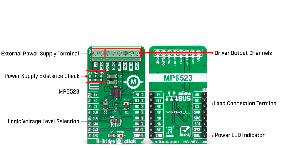
H-Bridge 10 Click
Dev. board
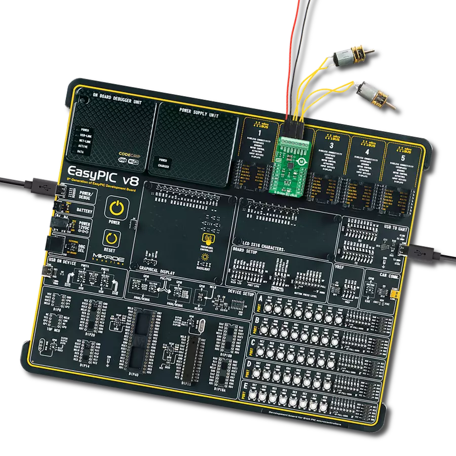
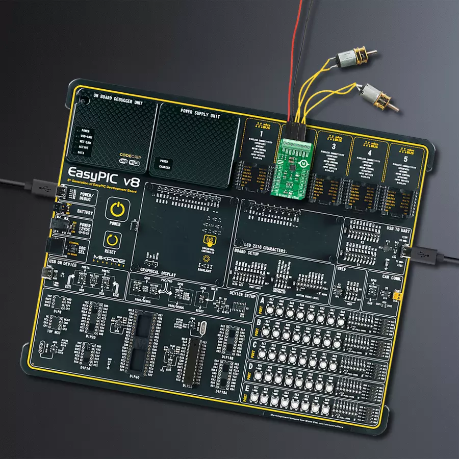
EasyPIC v8
Compiler
NECTO Studio
MCU
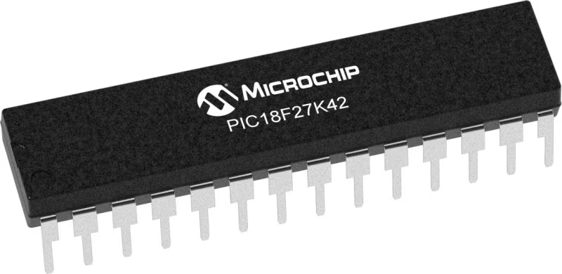
PIC18F27K42
The ultimate solution for precision motor control and seamless switching
A
A
Hardware Overview
How does it work?
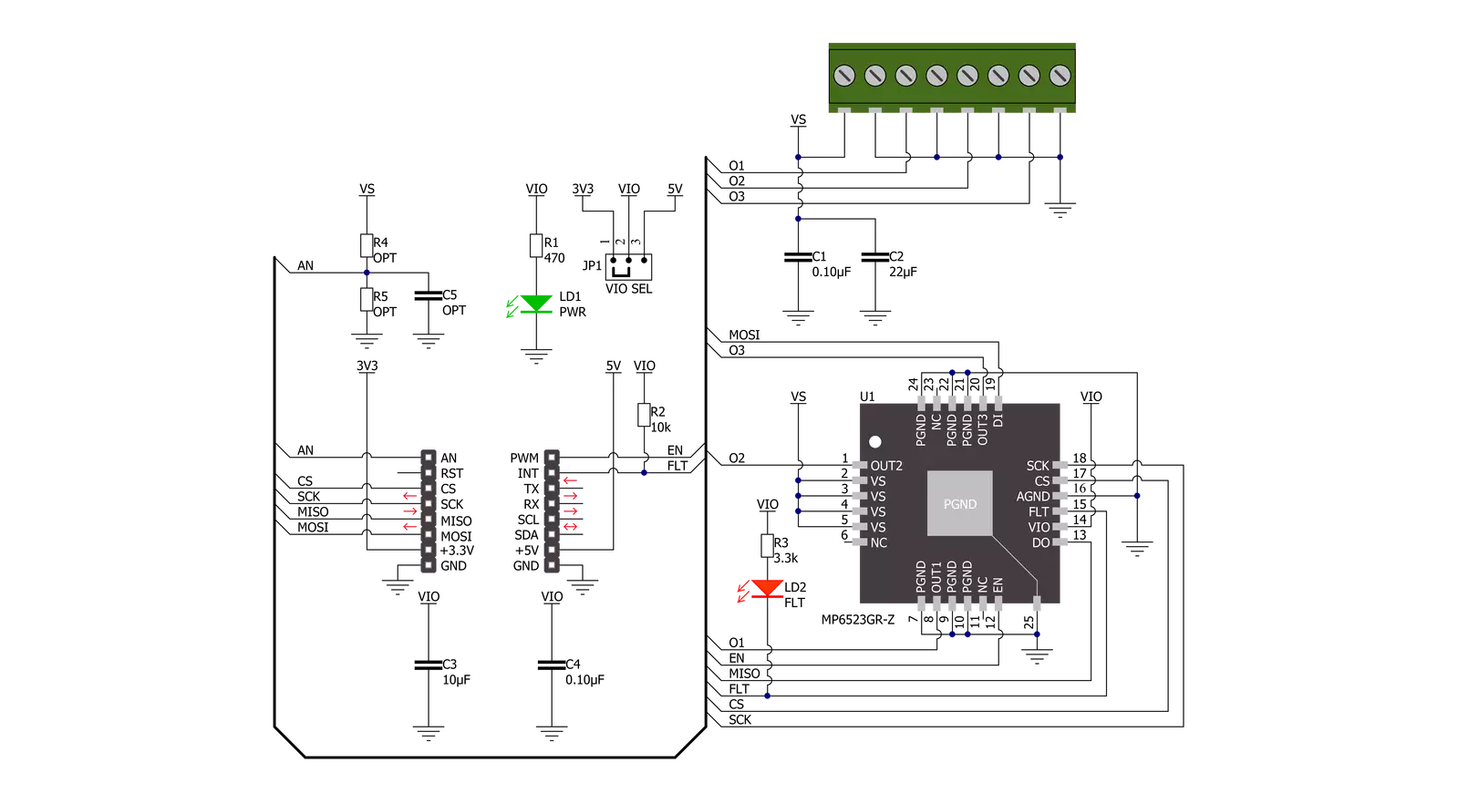
H-Bridge 10 Click is based on the MP6523, a triple, half-bridge motor driver from Monolithic Power Systems (MPS). The MP6523 contains three MOSFET half-bridge outputs that can drive up to three different loads with separate controls for high-side or low-side MOSFETs from a standard serial data interface. It has a low quiescent current in standby mode, making it suitable for many applications. The input voltage ranges from 7V to 28V, with up to 0.9A output current capability per channel. Complete protection features include short-circuiting protection, under-voltage protection, and thermal shutdown.
This Click board™ communicates with MCU through a standard SPI interface and operates at clock rates up to 3MHz, providing data in a digital format of 16 bits. It also can be enabled or disabled through the EN pin of the mikroBUS™ socket, hence, offering a switch operation to turn ON/OFF power delivery to the MP6523. It also provides a fault status indication signal, labeled as FLT and routed to the INT pin of the mikroBUS™ socket, alongside its red LED indicator marked as FLT to indicate different fault conditions such as current limit and thermal shutdown. A unique addition that this board has is checking the
existence of an external power supply. By adding resistors R4 and R5, the user can monitor and check the presence of an external power supply on the VS terminal via the voltage divider routed to the AN pin of the mikroBUS™ socket. This Click board™ can operate with either 3.3V or 5V logic voltage levels selected via the VCC SEL jumper. This way, both 3.3V and 5V capable MCUs can use the communication lines properly. However, the Click board™ comes equipped with a library containing easy-to-use functions and an example code that can be used, as a reference, for further development.
Features overview
Development board
EasyPIC v8 is a development board specially designed for the needs of rapid development of embedded applications. It supports many high pin count 8-bit PIC microcontrollers from Microchip, regardless of their number of pins, and a broad set of unique functions, such as the first-ever embedded debugger/programmer. The development board is well organized and designed so that the end-user has all the necessary elements, such as switches, buttons, indicators, connectors, and others, in one place. Thanks to innovative manufacturing technology, EasyPIC v8 provides a fluid and immersive working experience, allowing access anywhere and under any
circumstances at any time. Each part of the EasyPIC v8 development board contains the components necessary for the most efficient operation of the same board. In addition to the advanced integrated CODEGRIP programmer/debugger module, which offers many valuable programming/debugging options and seamless integration with the Mikroe software environment, the board also includes a clean and regulated power supply module for the development board. It can use a wide range of external power sources, including a battery, an external 12V power supply, and a power source via the USB Type-C (USB-C) connector.
Communication options such as USB-UART, USB DEVICE, and CAN are also included, including the well-established mikroBUS™ standard, two display options (graphical and character-based LCD), and several different DIP sockets. These sockets cover a wide range of 8-bit PIC MCUs, from the smallest PIC MCU devices with only eight up to forty pins. EasyPIC v8 is an integral part of the Mikroe ecosystem for rapid development. Natively supported by Mikroe software tools, it covers many aspects of prototyping and development thanks to a considerable number of different Click boards™ (over a thousand boards), the number of which is growing every day.

Microcontroller Overview
MCU Card / MCU
Architecture
PIC
MCU Memory (KB)
128
Silicon Vendor
Microchip
Pin count
28
RAM (Bytes)
8192
You complete me!
Accessories
DC Gear Motor - 430RPM (3-6V) represents an all-in-one combination of a motor and gearbox, where the addition of gear leads to a reduction of motor speed while increasing the torque output. This gear motor has a spur gearbox, making it a highly reliable solution for applications with lower torque and speed requirements. The most critical parameters for gear motors are speed, torque, and efficiency, which are, in this case, 520RPM with no load and 430RPM at maximum efficiency, alongside a current of 60mA and a torque of 50g.cm. Rated for a 3-6V operational voltage range and clockwise/counterclockwise rotation direction, this motor represents an excellent solution for many functions initially performed by brushed DC motors in robotics, medical equipment, electric door locks, and much more.

Used MCU Pins
mikroBUS™ mapper
Take a closer look
Click board™ Schematic
Step by step
Project assembly

Start by selecting your development board and Click board™. Begin with the EasyPIC v8 as your development board.


Software Support
Library Description
This library contains API for H-Bridge 10 Click driver.
Key functions:
hbridge10_set_output_stateThis function sets the output channel state.hbridge10_get_statusThis function reads the status of output register.hbridge10_get_fault_pinThis function returns the fault (FLT) pin logic state.
Open Source
Code example
The complete application code and a ready-to-use project are available through the NECTO Studio Package Manager for direct installation in the NECTO Studio. The application code can also be found on the MIKROE GitHub account.
/*!
 * @file main.c
 * @brief HBridge10 Click example
 *
 * # Description
 * This example demonstrates the use of the H-Bridge 10 Click board by
 * driving the motors connected between OUT1-OUT2 and OUT2-OUT3 in both directions.
 *
 * The demo application is composed of two sections :
 *
 * ## Application Init
 * Initializes the driver and performs the Click default configuration.
 *
 * ## Application Task
 * Drives the motors connected between OUT1-OUT2 and OUT2-OUT3 in both directions
 * in the span of 6 seconds, and displays the status messages on the USB UART.
 *
 * @author Stefan Filipovic
 *
 */

#include "board.h"
#include "log.h"
#include "hbridge10.h"

static hbridge10_t hbridge10;
static log_t logger;

/**
 * @brief H-Bridge 10 display status function.
 * @details This function parses the status from output register and displays it on the USB UART.
 * @param[in] status : 16-bit status value.
 * @return None.
 * @note None.
 */
void hbridge10_display_status ( uint16_t status );

void application_init ( void )
{
    log_cfg_t log_cfg;  /**< Logger config object. */
    hbridge10_cfg_t hbridge10_cfg;  /**< Click config object. */

    /**
     * Logger initialization.
     * Default baud rate: 115200
     * Default log level: LOG_LEVEL_DEBUG
     * @note If USB_UART_RX and USB_UART_TX
     * are defined as HAL_PIN_NC, you will
     * need to define them manually for log to work.
     * See @b LOG_MAP_USB_UART macro definition for detailed explanation.
     */
    LOG_MAP_USB_UART( log_cfg );
    log_init( &logger, &log_cfg );
    log_info( &logger, " Application Init " );

    // Click initialization.
    hbridge10_cfg_setup( &hbridge10_cfg );
    HBRIDGE10_MAP_MIKROBUS( hbridge10_cfg, MIKROBUS_1 );
    if ( SPI_MASTER_ERROR == hbridge10_init( &hbridge10, &hbridge10_cfg ) )
    {
        log_error( &logger, " Communication init." );
        for ( ; ; );
    }

    if ( HBRIDGE10_ERROR == hbridge10_default_cfg ( &hbridge10 ) )
    {
        log_error( &logger, " Default configuration." );
        for ( ; ; );
    }

    log_info( &logger, " Application Task " );
}

void application_task ( void )
{
    uint16_t status;
    if ( ( HBRIDGE10_OK == hbridge10_set_output_state ( &hbridge10, HBRIDGE10_CHANNEL_OUT1, HBRIDGE10_OUT_HIGH ) ) &&
         ( HBRIDGE10_OK == hbridge10_set_output_state ( &hbridge10, HBRIDGE10_CHANNEL_OUT2, HBRIDGE10_OUT_LOW ) ) &&
         ( HBRIDGE10_OK == hbridge10_set_output_state ( &hbridge10, HBRIDGE10_CHANNEL_OUT3, HBRIDGE10_OUT_HIGH ) ) )
    {
        Delay_ms ( 100 );
        if ( HBRIDGE10_OK == hbridge10_get_status ( &hbridge10, &status ) )
        {
            hbridge10_display_status ( status );
            Delay_ms ( 1000 );
            Delay_ms ( 1000 );
            Delay_ms ( 1000 );
        }
    }
    if ( ( HBRIDGE10_OK == hbridge10_set_output_state ( &hbridge10, HBRIDGE10_CHANNEL_OUT1, HBRIDGE10_OUT_LOW ) ) &&
         ( HBRIDGE10_OK == hbridge10_set_output_state ( &hbridge10, HBRIDGE10_CHANNEL_OUT2, HBRIDGE10_OUT_HIGH ) ) &&
         ( HBRIDGE10_OK == hbridge10_set_output_state ( &hbridge10, HBRIDGE10_CHANNEL_OUT3, HBRIDGE10_OUT_LOW ) ) )
    {
        Delay_ms ( 100 );
        if ( HBRIDGE10_OK == hbridge10_get_status ( &hbridge10, &status ) )
        {
            hbridge10_display_status ( status );
            Delay_ms ( 1000 );
            Delay_ms ( 1000 );
            Delay_ms ( 1000 );
        }
    }
}

int main ( void )
{
    /* Do not remove this line or clock might not be set correctly. */
    #ifdef PREINIT_SUPPORTED
    preinit();
    #endif

    application_init( );

    for ( ; ; )
    {
        application_task( );
    }

    return 0;
}

void hbridge10_display_status ( uint16_t status )
{
    if ( HBRIDGE10_OUT_OVER_TEMP_SD == status )
    {
        log_printf ( &logger, " Over temperature shutdown! \r\n" );
        return;
    }
    if ( status & HBRIDGE10_OUT_OVER_TEMP_WARNING )
    {
        log_printf ( &logger, " Over temperature pre-warning! \r\n" );
    }
    log_printf ( &logger, " OUT1 : " );
    if ( status & HBRIDGE10_OUT_STATUS_LS1_ON )
    {
        log_printf ( &logger, "LOW \r\n" );
    }
    else if ( status & HBRIDGE10_OUT_STATUS_HS1_ON )
    {
        log_printf ( &logger, "HIGH \r\n" );
    }
    else
    {
        log_printf ( &logger, "OFF \r\n" );
    }
    log_printf ( &logger, " OUT2 : " );
    if ( status & HBRIDGE10_OUT_STATUS_LS2_ON )
    {
        log_printf ( &logger, "LOW \r\n" );
    }
    else if ( status & HBRIDGE10_OUT_STATUS_HS2_ON )
    {
        log_printf ( &logger, "HIGH \r\n" );
    }
    else
    {
        log_printf ( &logger, "OFF \r\n" );
    }
    log_printf ( &logger, " OUT3 : " );
    if ( status & HBRIDGE10_OUT_STATUS_LS3_ON )
    {
        log_printf ( &logger, "LOW \r\n" );
    }
    else if ( status & HBRIDGE10_OUT_STATUS_HS3_ON )
    {
        log_printf ( &logger, "HIGH \r\n" );
    }
    else
    {
        log_printf ( &logger, "OFF \r\n" );
    }
    if ( status & HBRIDGE10_OUT_SHORT_CIRCUIT_DETECTED )
    {
        log_printf ( &logger, " Short circuit detected! \r\n" );
    }
    log_printf ( &logger, " Power : " );
    if ( HBRIDGE10_OUT_NORMAL_OPERATION != ( status & HBRIDGE10_OUT_NORMAL_OPERATION ) )
    {
        log_printf ( &logger, "Standby \r\n" );
    }
    else if ( status & HBRIDGE10_OUT_VS_UNDER_VOLTAGE )
    {
        log_printf ( &logger, "Under-voltage at VS detected \r\n" );
    }
    else
    {
        log_printf ( &logger, "Normal operation \r\n" );
    }
    log_printf ( &logger, "\r\n" );
}

// ------------------------------------------------------------------------ END


