Provide detailed information about power consumption and energy usage with INA700A and PIC18F25K50
High-performance power monitor based on EZShunt™ technology
Published Nov 18, 2024
Click board™
VCP Monitor 5 Click
Dev. board
EasyPIC v8
Compiler
NECTO Studio
MCU
PIC18F25K50
Monitor current, voltage, and temperature with high precision for accurate energy management
A
A
Hardware Overview
How does it work?
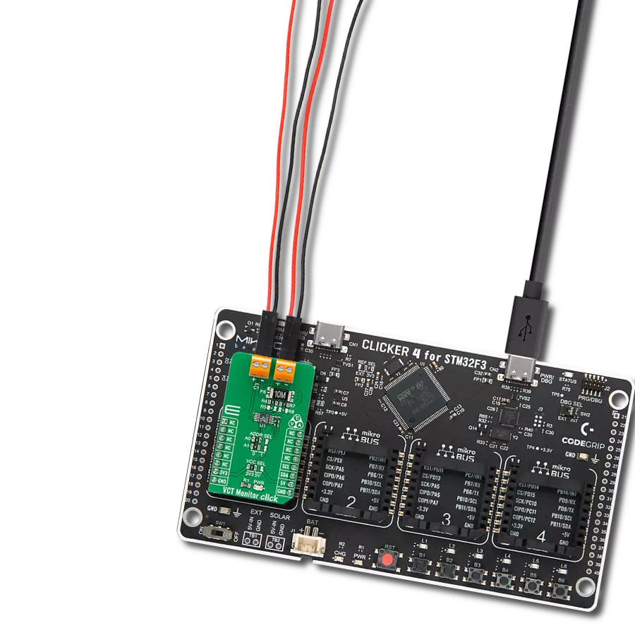
VCP Monitor 5 Click is based on the INA700A, a 16-bit digital power monitor from Texas Instruments built with advanced EZShunt™ technology. The INA700A integrates a precision shunt resistor and a high-resolution delta-sigma ADC designed specifically for accurate current sensing applications. This IC can handle full-scale current measurements of up to ±15.728A and operates within a broad common-mode voltage range from -0.3V to +40V, making it adaptable for various power monitoring needs. It is ideal for high-precision power monitoring applications, including industrial battery packs, smart network interface cards (NICs), and hardware accelerator cards, among other high-performance systems where accurate current and energy monitoring are essential. This power monitor accurately measures
and reports current, bus voltage, internal temperature, power, energy, and charge accumulation. Thanks to the integrated ±0.5% oscillator, it performs real-time calculations seamlessly in the background. The embedded temperature sensor provides an accuracy of ±3°C across the junction temperature range, ensuring reliable thermal monitoring under varying operating conditions. The device allows customization through selectable ADC conversion times ranging from 50µs to 4.12ms and sample averaging options from 1x to 1024x, significantly reducing measurement noise and improving the detection window for overcurrent events. VCP Monitor 5 Click uses a standard 2-wire I2C communication protocol to enable the host MCU to control the INA700A. The I2C interface supports clock frequencies up to
400kHz, with the I2C address selectable via the ADDR SEL jumpers. The alert interrupt ALR pin can be used to report multiple diagnostics whenever the monitored output value crosses the associated out-of-range threshold or to indicate that the ADC conversion is complete. Detected abnormalities such as current under/over-limit, bus voltage under/over-limit, or power over-limit, besides the ALR pin, can also be visually displayed by a red ALERT LED. This Click board™ can operate with either 3.3V or 5V logic voltage levels selected via the VCC SEL jumper. This way, both 3.3V and 5V capable MCUs can use the communication lines properly. Also, this Click board™ comes equipped with a library containing easy-to-use functions and an example code that can be used as a reference for further development.

Features overview
Development board
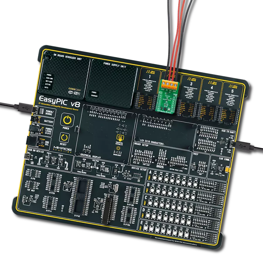
EasyPIC v8 is a development board specially designed for the needs of rapid development of embedded applications. It supports many high pin count 8-bit PIC microcontrollers from Microchip, regardless of their number of pins, and a broad set of unique functions, such as the first-ever embedded debugger/programmer. The development board is well organized and designed so that the end-user has all the necessary elements, such as switches, buttons, indicators, connectors, and others, in one place. Thanks to innovative manufacturing technology, EasyPIC v8 provides a fluid and immersive working experience, allowing access anywhere and under any
circumstances at any time. Each part of the EasyPIC v8 development board contains the components necessary for the most efficient operation of the same board. In addition to the advanced integrated CODEGRIP programmer/debugger module, which offers many valuable programming/debugging options and seamless integration with the Mikroe software environment, the board also includes a clean and regulated power supply module for the development board. It can use a wide range of external power sources, including a battery, an external 12V power supply, and a power source via the USB Type-C (USB-C) connector.
Communication options such as USB-UART, USB DEVICE, and CAN are also included, including the well-established mikroBUS™ standard, two display options (graphical and character-based LCD), and several different DIP sockets. These sockets cover a wide range of 8-bit PIC MCUs, from the smallest PIC MCU devices with only eight up to forty pins. EasyPIC v8 is an integral part of the Mikroe ecosystem for rapid development. Natively supported by Mikroe software tools, it covers many aspects of prototyping and development thanks to a considerable number of different Click boards™ (over a thousand boards), the number of which is growing every day.

Microcontroller Overview
MCU Card / MCU

Architecture
PIC
MCU Memory (KB)
32
Silicon Vendor
Microchip
Pin count
28
RAM (Bytes)
2048
Used MCU Pins
mikroBUS™ mapper
Take a closer look
Click board™ Schematic

Step by step
Project assembly

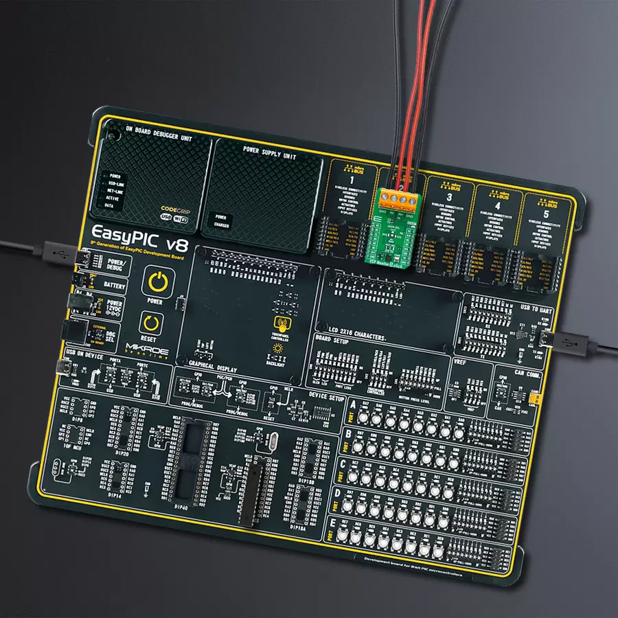
Start by selecting your development board and Click board™. Begin with the EasyPIC v8 as your development board.


Track your results in real time
Application Output
1. Application Output - In Debug mode, the 'Application Output' window enables real-time data monitoring, offering direct insight into execution results. Ensure proper data display by configuring the environment correctly using the provided tutorial.

2. UART Terminal - Use the UART Terminal to monitor data transmission via a USB to UART converter, allowing direct communication between the Click board™ and your development system. Configure the baud rate and other serial settings according to your project's requirements to ensure proper functionality. For step-by-step setup instructions, refer to the provided tutorial.

3. Plot Output - The Plot feature offers a powerful way to visualize real-time sensor data, enabling trend analysis, debugging, and comparison of multiple data points. To set it up correctly, follow the provided tutorial, which includes a step-by-step example of using the Plot feature to display Click board™ readings. To use the Plot feature in your code, use the function: plot(*insert_graph_name*, variable_name);. This is a general format, and it is up to the user to replace 'insert_graph_name' with the actual graph name and 'variable_name' with the parameter to be displayed.

Software Support
Library Description
This library contains API for VCP Monitor 5 Click driver.
Key functions:
vcpmonitor5_get_bus_voltage- This function reads the BUS voltage output measurement in volts [V] by using I2C serial interface.vcpmonitor5_get_current- This function reads the current measurement result in milliamperes [mA] by using the I2C serial interface.vcpmonitor5_get_power- This function reads the power measurement result in Watts [W] by using the I2C serial interface.
Open Source
Code example
The complete application code and a ready-to-use project are available through the NECTO Studio Package Manager for direct installation in the NECTO Studio. The application code can also be found on the MIKROE GitHub account.
/*!
 * @file main.c
 * @brief VCP Monitor 5 Click example
 *
 * # Description
 * This library contains API for the VCP Monitor 5 Click driver
 * for measurements of the voltage, current, power, energy, charge, and die temperature.
 *
 * The demo application is composed of two sections :
 *
 * ## Application Init
 * The initialization of the I2C module and log UART.
 * After driver initialization, the app sets the default configuration.
 *
 * ## Application Task
 * The demo application reads and displays the results of the input bus voltage,
 * current, power, energy, charge accumulation measurements, and die temperature.
 * Results are being sent to the UART Terminal, where you can track their changes.
 *
 * @author Nenad Filipovic
 *
 */

#include "board.h"
#include "log.h"
#include "vcpmonitor5.h"

static vcpmonitor5_t vcpmonitor5;
static log_t logger;

void application_init ( void )
{
    log_cfg_t log_cfg;  /**< Logger config object. */
    vcpmonitor5_cfg_t vcpmonitor5_cfg;  /**< Click config object. */

    /**
     * Logger initialization.
     * Default baud rate: 115200
     * Default log level: LOG_LEVEL_DEBUG
     * @note If USB_UART_RX and USB_UART_TX
     * are defined as HAL_PIN_NC, you will
     * need to define them manually for log to work.
     * See @b LOG_MAP_USB_UART macro definition for detailed explanation.
     */
    LOG_MAP_USB_UART( log_cfg );
    log_init( &logger, &log_cfg );
    log_info( &logger, " Application Init " );

    // Click initialization.
    vcpmonitor5_cfg_setup( &vcpmonitor5_cfg );
    VCPMONITOR5_MAP_MIKROBUS( vcpmonitor5_cfg, MIKROBUS_1 );
    if ( I2C_MASTER_ERROR == vcpmonitor5_init( &vcpmonitor5, &vcpmonitor5_cfg ) )
    {
        log_error( &logger, " Communication init." );
        for ( ; ; );
    }

    if ( VCPMONITOR5_ERROR == vcpmonitor5_default_cfg ( &vcpmonitor5 ) )
    {
        log_error( &logger, " Default configuration." );
        for ( ; ; );
    }

    log_info( &logger, " Application Task " );
}

void application_task ( void )
{
    float app_buf = 0;
    if ( VCPMONITOR5_OK == vcpmonitor5_get_bus_voltage( &vcpmonitor5, &app_buf ) )
    {
        log_printf( &logger, " Voltage: %.2f [V]\r\n", app_buf );
        Delay_ms ( 50 );
    }

    if ( VCPMONITOR5_OK == vcpmonitor5_get_current( &vcpmonitor5, &app_buf ) )
    {
        log_printf( &logger, " Current: %.2f [mA]\r\n", app_buf );
        Delay_ms ( 50 );
    }

    if ( VCPMONITOR5_OK == vcpmonitor5_get_power( &vcpmonitor5, &app_buf ) )
    {
        log_printf( &logger, " Power: %.2f [W]\r\n", app_buf );
        Delay_ms ( 50 );
    }

    if ( VCPMONITOR5_OK == vcpmonitor5_get_energy( &vcpmonitor5, &app_buf ) )
    {
        log_printf( &logger, " Energy: %.2f [kJ]\r\n", app_buf );
        Delay_ms ( 50 );
    }

    if ( VCPMONITOR5_OK == vcpmonitor5_get_charge( &vcpmonitor5, &app_buf ) )
    {
        log_printf( &logger, " Charge: %.2f [C]\r\n", app_buf );
        Delay_ms ( 50 );
    }

    if ( VCPMONITOR5_OK == vcpmonitor5_get_temperature( &vcpmonitor5, &app_buf ) )
    {
        log_printf( &logger, " Temperature: %.2f [degC]\r\n", app_buf );
        Delay_ms ( 50 );
    }
    log_printf( &logger, " ----------------------------\r\n" );
    Delay_ms ( 1000 );
    Delay_ms ( 1000 );
}

int main ( void )
{
    /* Do not remove this line or clock might not be set correctly. */
    #ifdef PREINIT_SUPPORTED
    preinit();
    #endif

    application_init( );

    for ( ; ; )
    {
        application_task( );
    }

    return 0;
}

// ------------------------------------------------------------------------ END
Additional Support
Resources
Category:Measurements