Turn your IoT vision into reality with BC95-G and PIC18LF25K42
Elevating efficiency with multiband NB technology

Published Nov 01, 2023
Click board™
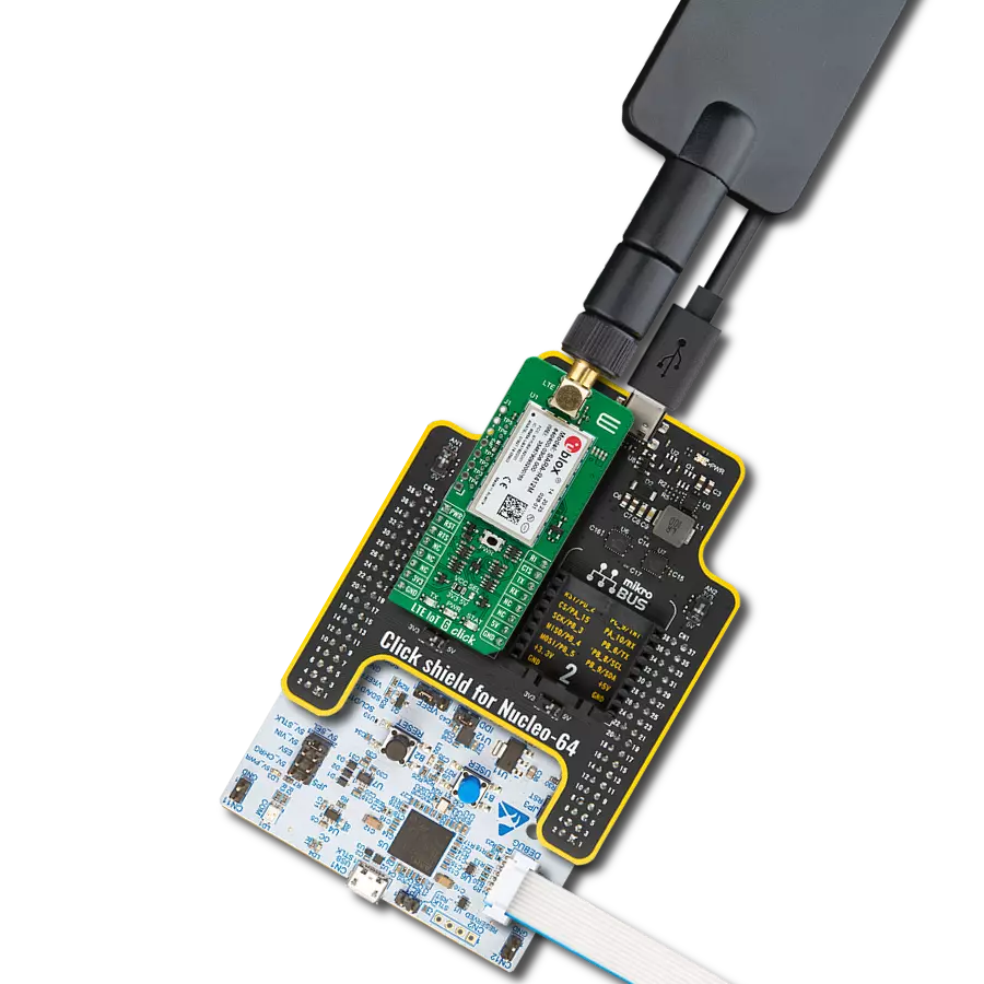
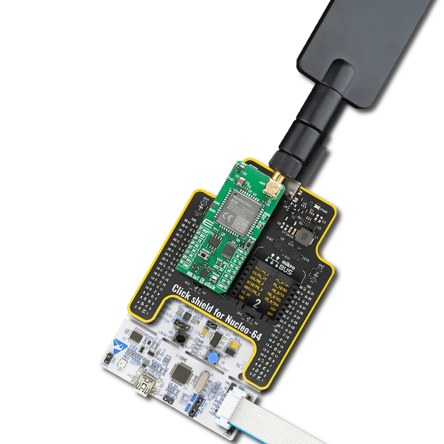
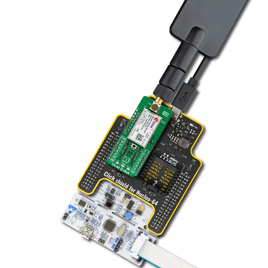
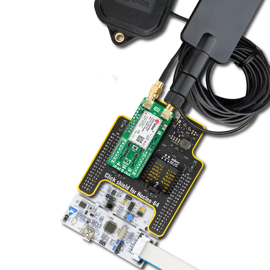
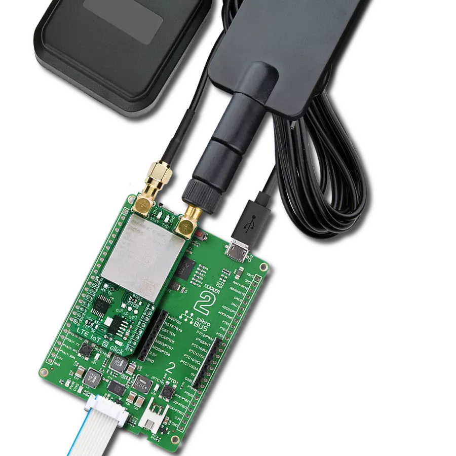
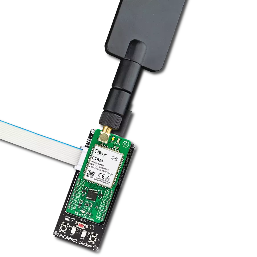
NB IoT Click
Dev. board
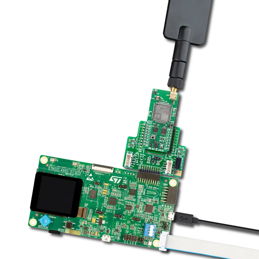
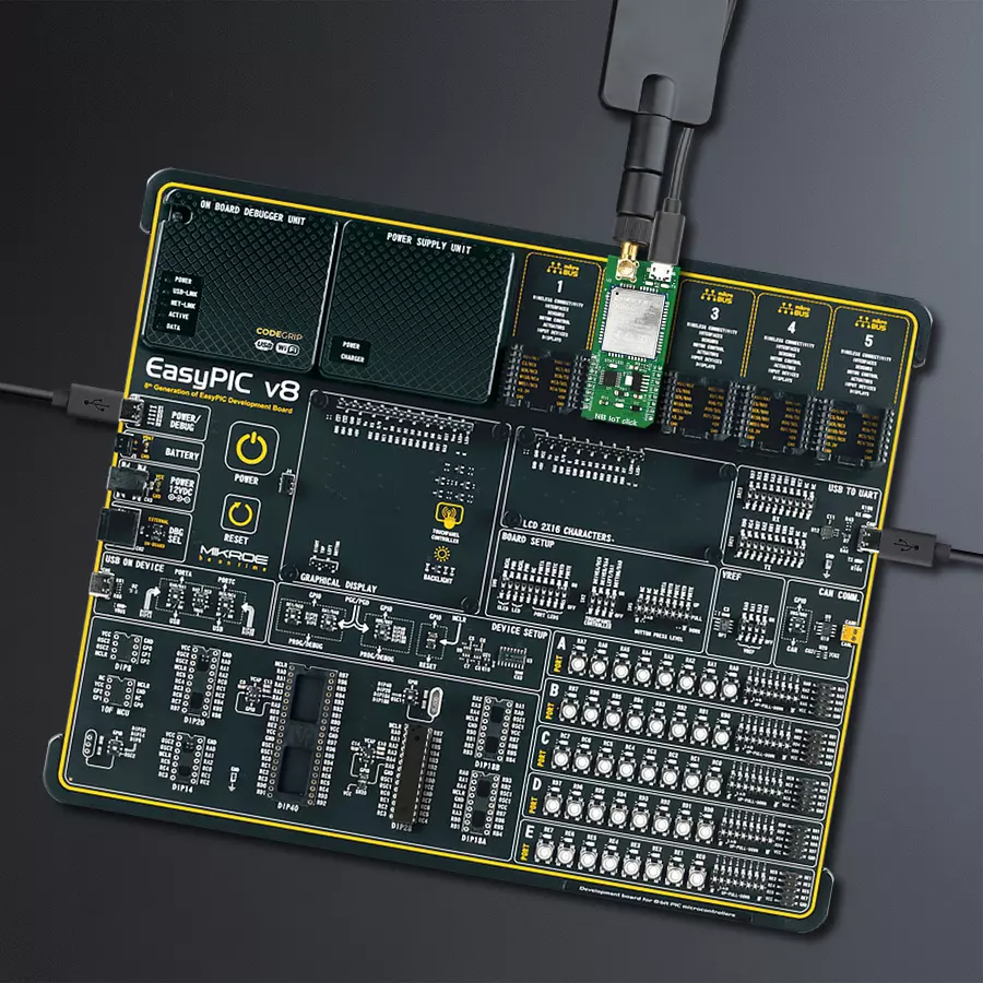
EasyPIC v8
Compiler
NECTO Studio
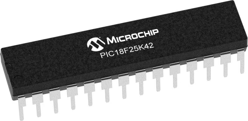
MCU
PIC18LF25K42
Reinvent connectivity, connect devices seamlessly, and achieve a new level of control and efficiency in your IoT projects
A
A
Hardware Overview
How does it work?
NB IoT Click is based on the BC95-G module from Quectel Wireless Solutions, which supports LTE NB1 technology, developed with IoT applications in mind. It supports several NB frequency bands: B1, B3, B5, B8, B20, and B28. The module supports point-to-point MO and MT messages, widely used for M2M communication. Packed with the set of protocols that allow data and SMS transfer using the NB1 technology and the ultra-low power consumption makes this module a perfect choice when it comes to building IoT applications. As mentioned before, BC95-G module is the main component of the click board and it consists of a number of internal blocks or sections, such as the RF Transceiver section, Flash SRAM section, Power Management section, and the cellular baseband processor with the peripheral interfaces. BC95 module supports several peripheral interfaces, including two UART interfaces (including the main UART and debug UART interface), USIM card interface, and GPIO interface. The main UART interface can be used for the AT command communication and data transmission. It supports baud rates of 9600 bps. The main UART interface can also be used for the firmware upgrade. In that case, a baud rate of 115200 bps is used. The Quectel BC95 module has to be powered by a clean and stable power supply. The voltage needed for the module to work properly is 4V and it is derived from the 5V mikroBUS™ rail, through the MCP1826, a 1A low drop output (LDO) regulator
from Microchip. Although the Quectel BC95 module is an ultra-low power device, its power consumption can briefly peak sometimes, so 1A LDO had to be used. The BC95 module does not have a dedicated USB interface, therefore a USB-to-UART circuit had to be added to the NB IoT click to provide USB to UART conversion. The FT230X, a highly integrated USB-UART bridge solution from FTDI is used, offering very simple integration thanks to its compact size and a small number of external components required. Two LEDs are used to signalize the data traffic through this IC: the red LED labeled as TX indicates the UART transmission, while the yellow LED labeled as RX indicates the UART reception. This Click board™ is equipped with the micro USB connector. It allows the module to be powered and configured by a personal computer. Quectel Wireless Solutions Company offers a software suite which can be used to configure the BC95 module. However, the FT230X IC requires drivers in order to work. FTDI offers drivers for all major OSes on their official driver download web page. Also, Windows OS drivers are included in the download section, below. The micro SIM card holder on the back of the Click board™ is used to install the SIM card. This device cannot be used without a valid SIM card which allows connection to the cellular network. Digital sections of the BC95 module are supplied with power by an integrated LDO regulator, so it is necessary to convert the logic
voltage level of the microcontroller (MCU) communication lines. By utilizing the LDO output (routed through the MOSFET switching circuitry), the needed reference voltage is provided for one side of the TXB0106, a 6bit bi-directional logic voltage level converter. The reference voltage for the other side of the TXB0106 is taken from the 3.3V power rail of the mikroBUS™. The small switching circuitry composed of a few signal-level MOSFETs is used to provide a way to switch off the FT230X when the Click board™ is inserted into the mikroBUS™ socket. This allows uninterrupted communication with the host MCU. The STAT pin is used to signalize the status of the device. This pin is routed both to the mikroBUS™ AN pin through the TXB0106 level translator, and the yellow LED labeled STAT, which is used to visually indicate the device status. The module can be reset by pulling the RST pin of the mikroBUS™ pin to a LOW logic level. This pin is pulled up to a HIGH level by an internal pull-up resistor. Besides the hardware reset, the module can also be reset by using the AT command. More information about the available AT commands can be found in the download section, below. However, the Click board™ comes supported by the mikroSDK library. The library contains functions which simplify the software development, integrating several AT commands into a single function call. Using mikroSDK makes the code way more readable, but more importantly - easily portable.

Features overview
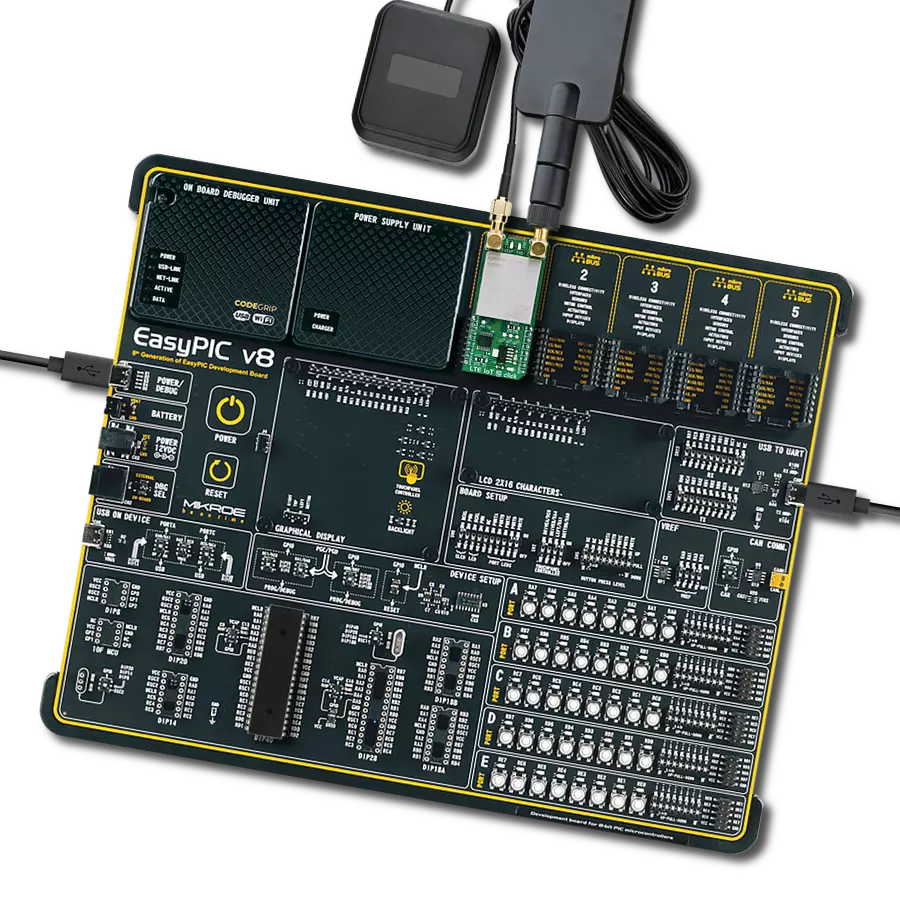
Development board
EasyPIC v8 is a development board specially designed for the needs of rapid development of embedded applications. It supports many high pin count 8-bit PIC microcontrollers from Microchip, regardless of their number of pins, and a broad set of unique functions, such as the first-ever embedded debugger/programmer. The development board is well organized and designed so that the end-user has all the necessary elements, such as switches, buttons, indicators, connectors, and others, in one place. Thanks to innovative manufacturing technology, EasyPIC v8 provides a fluid and immersive working experience, allowing access anywhere and under any
circumstances at any time. Each part of the EasyPIC v8 development board contains the components necessary for the most efficient operation of the same board. In addition to the advanced integrated CODEGRIP programmer/debugger module, which offers many valuable programming/debugging options and seamless integration with the Mikroe software environment, the board also includes a clean and regulated power supply module for the development board. It can use a wide range of external power sources, including a battery, an external 12V power supply, and a power source via the USB Type-C (USB-C) connector.
Communication options such as USB-UART, USB DEVICE, and CAN are also included, including the well-established mikroBUS™ standard, two display options (graphical and character-based LCD), and several different DIP sockets. These sockets cover a wide range of 8-bit PIC MCUs, from the smallest PIC MCU devices with only eight up to forty pins. EasyPIC v8 is an integral part of the Mikroe ecosystem for rapid development. Natively supported by Mikroe software tools, it covers many aspects of prototyping and development thanks to a considerable number of different Click boards™ (over a thousand boards), the number of which is growing every day.

Microcontroller Overview
MCU Card / MCU
Architecture
PIC
MCU Memory (KB)
32
Silicon Vendor
Microchip
Pin count
28
RAM (Bytes)
2048
You complete me!
Accessories
LTE Flat Rotation Antenna is a versatile choice for boosting the performance of 3G/4G LTE devices. With a wide frequency range of 700-2700MHz, it ensures optimal connectivity on major cellular bands worldwide. This flat antenna features an SMA male connector, making it easy to attach directly to your device or SMA module connector. One of its standout features is its adjustable angle, which can be set in 45⁰ increments (0⁰/45⁰/90⁰), allowing you to fine-tune the antenna's orientation for maximum signal reception. With an impedance of 50Ω and a VSW Ratio of <2.0:1, this antenna ensures a reliable and efficient connection. Its 5dB gain, vertical polarization, and omnidirectional radiation pattern enhance signal strength, making it suitable for various applications. Measuring 196mm in length and 38mm in width, this antenna offers a compact yet effective solution for improving your connectivity. With a maximum input power of 50W, it can handle the demands of various devices.

Used MCU Pins
mikroBUS™ mapper
Take a closer look
Click board™ Schematic

Step by step
Project assembly

Start by selecting your development board and Click board™. Begin with the EasyPIC v8 as your development board.


Software Support
Library Description
This library contains API for NB IoT Click driver.
Key functions:
nbiot_send_cmd- Send command functionnbiot_power_on- NB IoT module power onnbiot_generic_write- NB IoT data writing function
Open Source
Code example
The complete application code and a ready-to-use project are available through the NECTO Studio Package Manager for direct installation in the NECTO Studio. The application code can also be found on the MIKROE GitHub account.
/*!
 * \file
 * \brief NbIot Click example
 *
* # Description
 * This example reads and processes data from NB IoT Clicks.
 *
 * The demo application is composed of two sections :
 *
 * ## Application Init
 * Initializes driver, wake-up module and sets default configuration
 * for connecting device to network.
 *
 * ## Application Task
 * Waits for device to connect to network and then checks the signal quality
 * every 5 seconds. All data is being logged on USB UART where you can track their changes.
 *
 * ## Additional Function
 * - static void nbiot_clear_app_buf ( void )
 * - static void nbiot_error_check( err_t error_flag )
 * - static void nbiot_log_app_buf ( void )
 * - static void nbiot_check_connection( void )
 * - static err_t nbiot_rsp_check ( void )
 * - static err_t nbiot_process ( void )
 *
 * @note
 * In order for the example to work, a valid SIM card needs to be entered.
 *
 * @author MikroE Team
 *
 */
// ------------------------------------------------------------------- INCLUDES

#include "board.h"
#include "log.h"
#include "nbiot.h"

#define APP_OK                              0
#define APP_ERROR_DRIVER                    -1
#define APP_ERROR_OVERFLOW                  -2
#define APP_ERROR_TIMEOUT                   -3

#define RSP_OK                              "OK"
#define RSP_ERROR                           "ERROR"

#define PROCESS_BUFFER_SIZE                 500

#define WAIT_FOR_CONNECTION                 0
#define CONNECTED_TO_NETWORK                1

static nbiot_t nbiot;
static log_t logger;

static char app_buf[ PROCESS_BUFFER_SIZE ]  = { 0 };
static int32_t app_buf_len                  = 0;
static int32_t app_buf_cnt                  = 0;

static uint8_t app_connection_status        = WAIT_FOR_CONNECTION;

static err_t app_error_flag;

/**
 * @brief NB IoT clearing application buffer.
 * @details This function clears memory of application buffer and reset its length and counter.
 * @note None.
 */
static void nbiot_clear_app_buf ( void );

/**
 * @brief NB IoT data reading function.
 * @details This function reads data from device and concats data to application buffer.
 *
 * @return @li @c  0 - Read some data.
 *         @li @c -1 - Nothing is read.
 *         @li @c -2 - Application buffer overflow.
 *
 * See #err_t definition for detailed explanation.
 * @note None.
 */
static err_t nbiot_process ( void );

/**
 * @brief NB IoT check for errors.
 * @details This function checks for different types of errors and logs them on UART.
 * @note None.
 */
static void nbiot_error_check( err_t error_flag );

/**
 * @brief NB IoT logs application buffer.
 * @details This function logs data from application buffer.
 * @note None.
 */
static void nbiot_log_app_buf ( void );

/**
 * @brief NB IoT response check.
 * @details This function checks for response and returns the status of response.
 *
 * @return application status.
 * See #err_t definition for detailed explanation.
 * @note None.
 */
static err_t nbiot_rsp_check ( void );

/**
 * @brief NB IoT chek connection.
 * @details This function checks connection to the network and
 *          logs that status to UART.
 *
 * @note None.
 */
static void nbiot_check_connection( void );

// ------------------------------------------------------ APPLICATION FUNCTIONS

void application_init ( void )
{
    log_cfg_t log_cfg;  /**< Logger config object. */
    nbiot_cfg_t nbiot_cfg;  /**< Click config object. */

    /**
     * Logger initialization.
     * Default baud rate: 115200
     * Default log level: LOG_LEVEL_DEBUG
     * @note If USB_UART_RX and USB_UART_TX
     * are defined as HAL_PIN_NC, you will
     * need to define them manually for log to work.
     * See @b LOG_MAP_USB_UART macro definition for detailed explanation.
     */
    LOG_MAP_USB_UART( log_cfg );
    log_init( &logger, &log_cfg );
    log_info( &logger, " Application Init " );
    Delay_ms ( 1000 );

    // Click initialization.
    nbiot_cfg_setup( &nbiot_cfg );
    NBIOT_MAP_MIKROBUS( nbiot_cfg, MIKROBUS_1 );
    err_t init_flag  = nbiot_init( &nbiot, &nbiot_cfg );
    if ( init_flag == UART_ERROR )
    {
        log_error( &logger, " Application Init Error. " );
        log_info( &logger, " Please, run program again... " );

        for ( ; ; );
    }

    log_info( &logger, " Power on device... " );
    nbiot_power_on( &nbiot );
    // dummy read
    app_error_flag = nbiot_rsp_check(  );
    nbiot_error_check( app_error_flag );

    // AT
    nbiot_send_cmd( &nbiot, NBIOT_CMD_AT );
    app_error_flag = nbiot_rsp_check( );
    nbiot_error_check( app_error_flag );
    Delay_ms ( 500 );

    // ATI - product information
    nbiot_send_cmd( &nbiot, NBIOT_CMD_ATI );
    app_error_flag = nbiot_rsp_check(  );
    nbiot_error_check( app_error_flag );
    Delay_ms ( 500 );

    // CGMR - firmware version
    nbiot_send_cmd( &nbiot, NBIOT_CMD_CGMR );
    app_error_flag = nbiot_rsp_check(  );
    nbiot_error_check( app_error_flag );
    Delay_ms ( 1000 );

    // COPS - deregister from network
    nbiot_send_cmd_with_parameter( &nbiot, NBIOT_CMD_COPS, "2" );
    app_error_flag = nbiot_rsp_check(  );
    nbiot_error_check( app_error_flag );
    Delay_ms ( 1000 );

    // CFUN - full funtionality
    nbiot_send_cmd_with_parameter( &nbiot, NBIOT_CMD_CFUN, "1" );
    app_error_flag = nbiot_rsp_check(  );
    nbiot_error_check( app_error_flag );
    Delay_ms ( 500 );

    // COPS - automatic mode
    nbiot_send_cmd_with_parameter( &nbiot, NBIOT_CMD_COPS, "0" );
    app_error_flag = nbiot_rsp_check(  );
    nbiot_error_check( app_error_flag );
    Delay_ms ( 1000 );
    Delay_ms ( 1000 );

    // CEREG - network registration status
    nbiot_send_cmd_with_parameter( &nbiot, NBIOT_CMD_CEREG, "2" );
    app_error_flag = nbiot_rsp_check(  );
    nbiot_error_check( app_error_flag );
    Delay_ms ( 500 );

    // CIMI - request IMSI
    nbiot_send_cmd( &nbiot, NBIOT_CMD_CIMI );
    app_error_flag = nbiot_rsp_check(  );
    nbiot_error_check( app_error_flag );
    Delay_ms ( 500 );

    app_buf_len = 0;
    app_buf_cnt = 0;
    app_connection_status = WAIT_FOR_CONNECTION;
    log_info( &logger, " Application Task " );
    Delay_ms ( 1000 );
    Delay_ms ( 1000 );
    Delay_ms ( 1000 );
    Delay_ms ( 1000 );
    Delay_ms ( 1000 );
}

void application_task ( void )
{
    if ( app_connection_status == WAIT_FOR_CONNECTION )
    {
        // CGATT - request IMSI
        nbiot_send_cmd_check( &nbiot, NBIOT_CMD_CGATT );
        app_error_flag = nbiot_rsp_check(  );
        nbiot_error_check( app_error_flag );
        Delay_ms ( 500 );

        // CEREG - network registration status
        nbiot_send_cmd_check( &nbiot, NBIOT_CMD_CEREG );
        app_error_flag = nbiot_rsp_check(  );
        nbiot_error_check( app_error_flag );
        Delay_ms ( 500 );

        // CSQ - signal quality
        nbiot_send_cmd( &nbiot, NBIOT_CMD_CSQ );
        app_error_flag = nbiot_rsp_check(  );
        nbiot_error_check( app_error_flag );
        Delay_ms ( 1000 );
        Delay_ms ( 1000 );
        Delay_ms ( 1000 );
        Delay_ms ( 1000 );
        Delay_ms ( 1000 );
    }
    else
    {
        log_info( &logger, "CONNECTED TO NETWORK" );

        log_info( &logger, "CHECKING SIGNAL QUALITY" );
        nbiot_send_cmd( &nbiot, NBIOT_CMD_CSQ );
        app_error_flag = nbiot_rsp_check(  );
        nbiot_error_check( app_error_flag );
        Delay_ms ( 1000 );
        Delay_ms ( 1000 );
        Delay_ms ( 1000 );
        Delay_ms ( 1000 );
        Delay_ms ( 1000 );
    }
}

int main ( void )
{
    /* Do not remove this line or clock might not be set correctly. */
    #ifdef PREINIT_SUPPORTED
    preinit();
    #endif

    application_init( );

    for ( ; ; )
    {
        application_task( );
    }

    return 0;
}

static void nbiot_clear_app_buf ( void )
{
    memset( app_buf, 0, app_buf_len );
    app_buf_len = 0;
    app_buf_cnt = 0;
}

static err_t nbiot_process ( void )
{
    err_t return_flag = APP_ERROR_DRIVER;
    int32_t rx_size;
    char rx_buff[ PROCESS_BUFFER_SIZE ] = { 0 };

    rx_size = nbiot_generic_read( &nbiot, rx_buff, PROCESS_BUFFER_SIZE );

    if ( rx_size > 0 )
    {
        int32_t buf_cnt = 0;
        return_flag = APP_OK;

        if ( app_buf_len + rx_size >= PROCESS_BUFFER_SIZE )
        {
            nbiot_clear_app_buf(  );
            return_flag = APP_ERROR_OVERFLOW;
        }
        else
        {
            buf_cnt = app_buf_len;
            app_buf_len += rx_size;
        }

        for ( int32_t rx_cnt = 0; rx_cnt < rx_size; rx_cnt++ )
        {
            if ( rx_buff[ rx_cnt ] != 0 )
            {
                app_buf[ ( buf_cnt + rx_cnt ) ] = rx_buff[ rx_cnt ];
            }
            else
            {
                app_buf_len--;
                buf_cnt--;
            }
        }
    }

    return return_flag;
}

static err_t nbiot_rsp_check ( void )
{
    uint16_t timeout_cnt = 0;
    uint16_t timeout = 20000;

    err_t error_flag = nbiot_process(  );

    if ( ( error_flag != 0 ) && ( error_flag != -1 ) )
    {
        return error_flag;
    }

    while ( ( strstr( app_buf, RSP_OK ) == 0 ) && ( strstr( app_buf, RSP_ERROR ) == 0 ) )
    {
        error_flag = nbiot_process(  );
        if ( ( error_flag != 0 ) && ( error_flag != -1 ) )
        {
            return error_flag;
        }

        timeout_cnt++;
        if ( timeout_cnt > timeout )
        {
            while ( ( strstr( app_buf, RSP_OK ) == 0 ) && ( strstr( app_buf, RSP_ERROR ) == 0 ) )
            {
                nbiot_send_cmd( &nbiot, NBIOT_CMD_AT );
                nbiot_process(  );
                Delay_ms ( 100 );
            }
            nbiot_clear_app_buf(  );
            return APP_ERROR_TIMEOUT;
        }

        Delay_ms ( 1 );
    }

    nbiot_check_connection();

    nbiot_log_app_buf();

    log_printf( &logger, "-----------------------------------\r\n" );

    return APP_OK;
}

static void nbiot_error_check( err_t error_flag )
{
    if ( ( error_flag != 0 ) && ( error_flag != -1 ) )
    {
        switch ( error_flag )
        {
            case -2:
                log_error( &logger, " Overflow!" );
                break;
            case -3:
                log_error( &logger, " Timeout!" );
                break;
            default:
                break;
        }
    }
}

static void nbiot_log_app_buf ( void )
{
    for ( int32_t buf_cnt = 0; buf_cnt < app_buf_len; buf_cnt++ )
    {
        log_printf( &logger, "%c", app_buf[ buf_cnt ] );
    }
    log_printf( &logger, "\r\n" );
    nbiot_clear_app_buf(  );
}

static void nbiot_check_connection( void )
{
    #define CONNECTED "+CGATT:1"

    if ( strstr( app_buf, CONNECTED ) != 0 )
    {
        app_connection_status = CONNECTED_TO_NETWORK;
    }
}

// ------------------------------------------------------------------------ END