Create a compact bridge to I2C devices with FT201X and PIC18F2455
Full speed USB to I2C bridge
Published Nov 01, 2023
Click board™
USB to I2C 2 Click
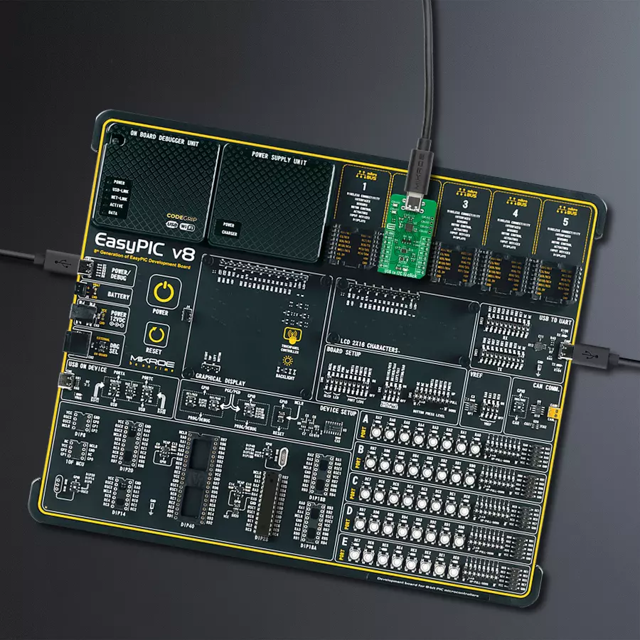
Dev. board
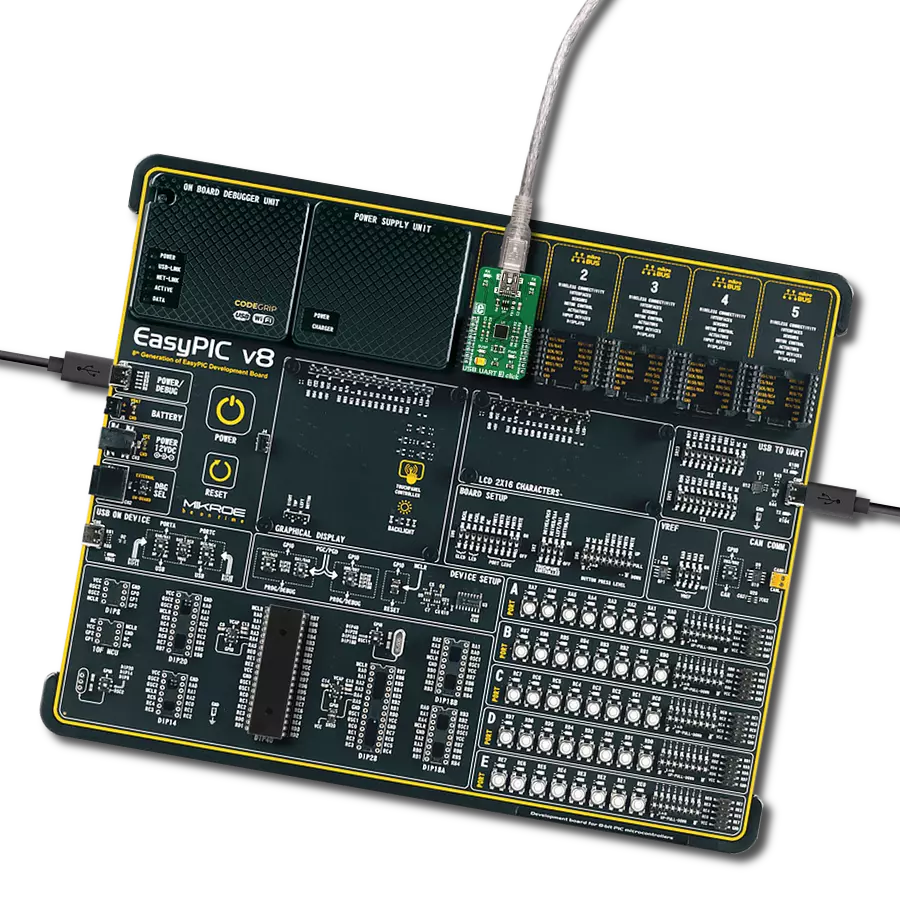
EasyPIC v8
Compiler
NECTO Studio
MCU
PIC18F2455
Discover the power of full-speed USB to I2C bridge and elevate your solution to new heights
A
A
Hardware Overview
How does it work?
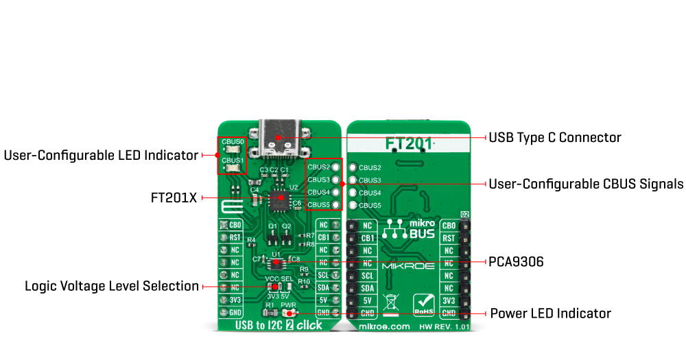
USB to I2C 2 Click is based on the FT201X, a USB to I2C interface device which simplifies USB implementations from FTDI. The FT201X is USB 2.0 full-speed compatible and handles the entire USB protocol by itself; no USB-specific firmware programming is required. It fully integrates 2048-byte Multi-Time-Programmable (MTP) memory for storing device descriptors, CBUS I/O user-desirable configuration, clock generation with no external crystal required, and optional clock output selection enabling a glue-less interface to external MCU or FPGA. This Click board™ communicates with MCU using the standard I2C 2-Wire interface to read data and configure settings, supporting Standard Mode operation with a clock frequency of 100kHz and Fast Mode up to 400kHz.
Since the FT201X for proper operation requires a 5V only, this Click board™ also features the PCA9306 voltage-level translator from Texas Instruments. The I2C interface bus lines are routed to the dual bidirectional voltage-level translator, allowing this Click board™ to work properly with both 3.3V and 5V MCUs. The FT201X also contains an embedded fully integrated MTP memory used to specify the functionality of the Control Bus (CBUS) pins, the current drive on each signal pin, the current limit for the USB bus, and the descriptors of the device. There are six configurable CBUS I/O pins, two routed on default AN and INT pins of the mikroBUS™ socket, marked as CB0 and CB1, alongside the two blue LED indicators labeled as CBUS0 and CBUS1 used for optional user-configurable
visual indication. The other four CBUS pins can be found on the onboard CBUS header and be used as user-configurable CBUS signals. A wide range and the way of using these pins can be found in the attached datasheet. This board also uses an active-low reset signal routed on the RST pin of the mikroBUS™ socket, which provides a reliable Power-On reset to the device's internal circuitry at Power-Up. This Click board™ can operate with either 3.3V or 5V logic voltage levels selected via the VCC SEL jumper. This way, both 3.3V and 5V capable MCUs can use the communication lines properly. However, the Click board™ comes equipped with a library containing easy-to-use functions and an example code that can be used, as a reference, for further development.
Features overview
Development board
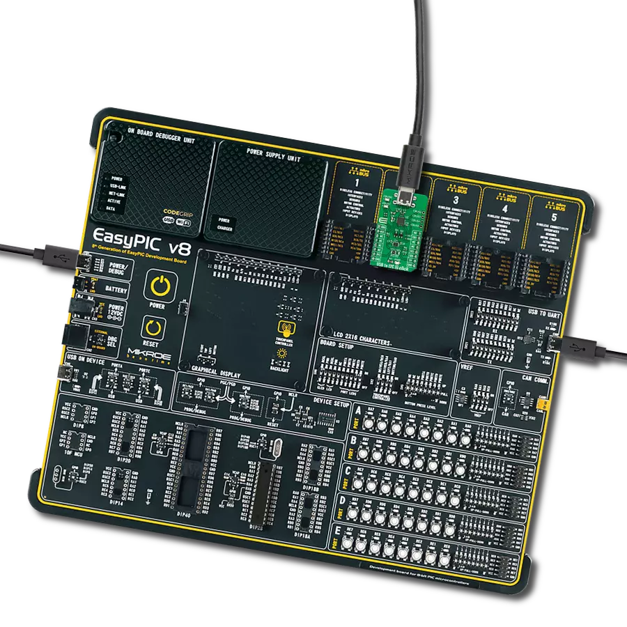
EasyPIC v8 is a development board specially designed for the needs of rapid development of embedded applications. It supports many high pin count 8-bit PIC microcontrollers from Microchip, regardless of their number of pins, and a broad set of unique functions, such as the first-ever embedded debugger/programmer. The development board is well organized and designed so that the end-user has all the necessary elements, such as switches, buttons, indicators, connectors, and others, in one place. Thanks to innovative manufacturing technology, EasyPIC v8 provides a fluid and immersive working experience, allowing access anywhere and under any
circumstances at any time. Each part of the EasyPIC v8 development board contains the components necessary for the most efficient operation of the same board. In addition to the advanced integrated CODEGRIP programmer/debugger module, which offers many valuable programming/debugging options and seamless integration with the Mikroe software environment, the board also includes a clean and regulated power supply module for the development board. It can use a wide range of external power sources, including a battery, an external 12V power supply, and a power source via the USB Type-C (USB-C) connector.
Communication options such as USB-UART, USB DEVICE, and CAN are also included, including the well-established mikroBUS™ standard, two display options (graphical and character-based LCD), and several different DIP sockets. These sockets cover a wide range of 8-bit PIC MCUs, from the smallest PIC MCU devices with only eight up to forty pins. EasyPIC v8 is an integral part of the Mikroe ecosystem for rapid development. Natively supported by Mikroe software tools, it covers many aspects of prototyping and development thanks to a considerable number of different Click boards™ (over a thousand boards), the number of which is growing every day.

Microcontroller Overview
MCU Card / MCU

Architecture
PIC
MCU Memory (KB)
24
Silicon Vendor
Microchip
Pin count
28
RAM (Bytes)
2048
Used MCU Pins
mikroBUS™ mapper
Take a closer look
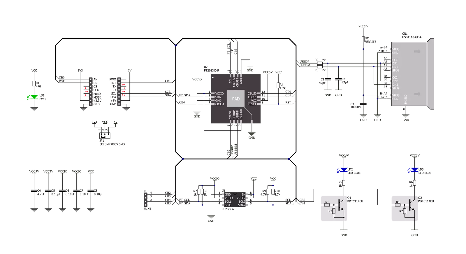
Click board™ Schematic
Step by step
Project assembly

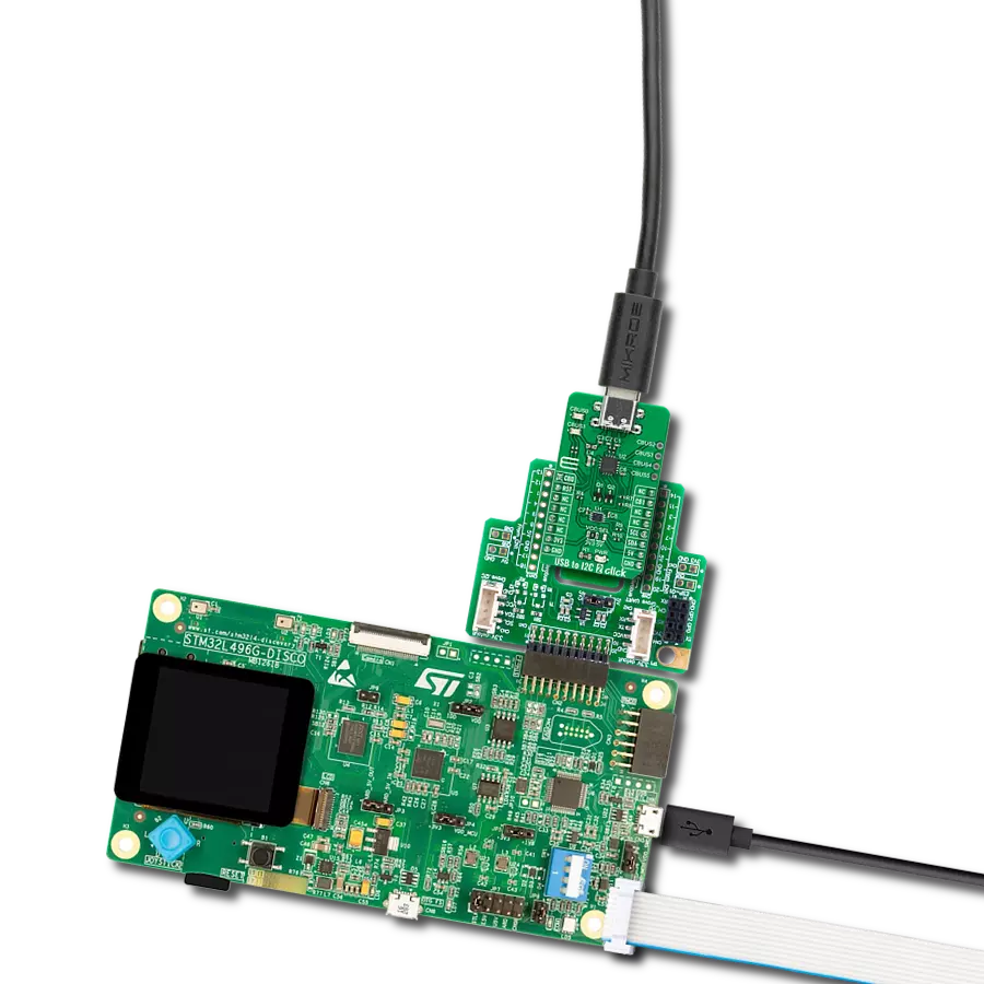
Start by selecting your development board and Click board™. Begin with the EasyPIC v8 as your development board.


Software Support
Library Description
This library contains API for USB to I2C 2 Click driver.
Key functions:
usbtoi2c2_write_dataThis function writes a desired number of data bytes by using I2C serial interface.usbtoi2c2_read_dataThis function reads a desired number of data bytes by using I2C serial interface.usbtoi2c2_reset_deviceThis function resets the device by toggling the RST pin state.
Open Source
Code example
The complete application code and a ready-to-use project are available through the NECTO Studio Package Manager for direct installation in the NECTO Studio. The application code can also be found on the MIKROE GitHub account.
/*!
 * @file main.c
 * @brief USBtoI2C2 Click example
 *
 * # Description
 * This example demonstrates the use of USB to I2C 2 Click by echoing back all
 * the received messages.
 *
 * The demo application is composed of two sections :
 *
 * ## Application Init
 * Initializes the driver and performs the Click default configuration.
 *
 * ## Application Task
 * Any data which the host PC sends to the Virtual COM Port (for example, typed into the terminal
 * window in UART Terminal) will be sent over USB to the Click board and then it will be read and
 * echoed back by the MCU to the PC where the terminal program will display it.
 *
 * @note
 * Make sure to download and install appropriate VCP drivers on the host PC.
 *
 * @author Stefan Filipovic
 *
 */

#include "board.h"
#include "log.h"
#include "usbtoi2c2.h"

static usbtoi2c2_t usbtoi2c2;
static log_t logger;

void application_init ( void )
{
    log_cfg_t log_cfg;  /**< Logger config object. */
    usbtoi2c2_cfg_t usbtoi2c2_cfg;  /**< Click config object. */

    /**
     * Logger initialization.
     * Default baud rate: 115200
     * Default log level: LOG_LEVEL_DEBUG
     * @note If USB_UART_RX and USB_UART_TX
     * are defined as HAL_PIN_NC, you will
     * need to define them manually for log to work.
     * See @b LOG_MAP_USB_UART macro definition for detailed explanation.
     */
    LOG_MAP_USB_UART( log_cfg );
    log_init( &logger, &log_cfg );
    log_info( &logger, " Application Init " );

    // Click initialization.
    usbtoi2c2_cfg_setup( &usbtoi2c2_cfg );
    USBTOI2C2_MAP_MIKROBUS( usbtoi2c2_cfg, MIKROBUS_1 );
    if ( I2C_MASTER_ERROR == usbtoi2c2_init( &usbtoi2c2, &usbtoi2c2_cfg ) )
    {
        log_error( &logger, " Communication init." );
        for ( ; ; );
    }

    if ( USBTOI2C2_ERROR == usbtoi2c2_default_cfg ( &usbtoi2c2 ) )
    {
        log_error( &logger, " Default configuration." );
        for ( ; ; );
    }

    log_info( &logger, " Application Task " );
}

void application_task ( void )
{
    uint8_t rx_data = 0;
    if ( USBTOI2C2_OK == usbtoi2c2_read_data ( &usbtoi2c2, &rx_data, 1 ) )
    {
        if ( USBTOI2C2_OK == usbtoi2c2_write_data ( &usbtoi2c2, &rx_data, 1 ) )
        {
            log_printf( &logger, "%c", rx_data );
        }
    }
}

int main ( void )
{
    /* Do not remove this line or clock might not be set correctly. */
    #ifdef PREINIT_SUPPORTED
    preinit();
    #endif

    application_init( );

    for ( ; ; )
    {
        application_task( );
    }

    return 0;
}

// ------------------------------------------------------------------------ END