Experience adaptive lighting tailored to your environment using VEML6030 and PIC18F26K40
Brighter, Smarter, Better!
Published Nov 01, 2023
Click board™
Ambient 5 Click
Dev. board
EasyPIC v7a
Compiler
NECTO Studio
MCU
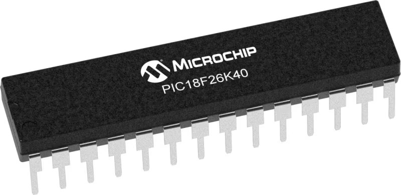
PIC18F26K40
Discover how our ambient light sensing solution enhances energy efficiency and user comfort by dynamically adjusting lighting conditions to the surrounding environment
A
A
Hardware Overview
How does it work?
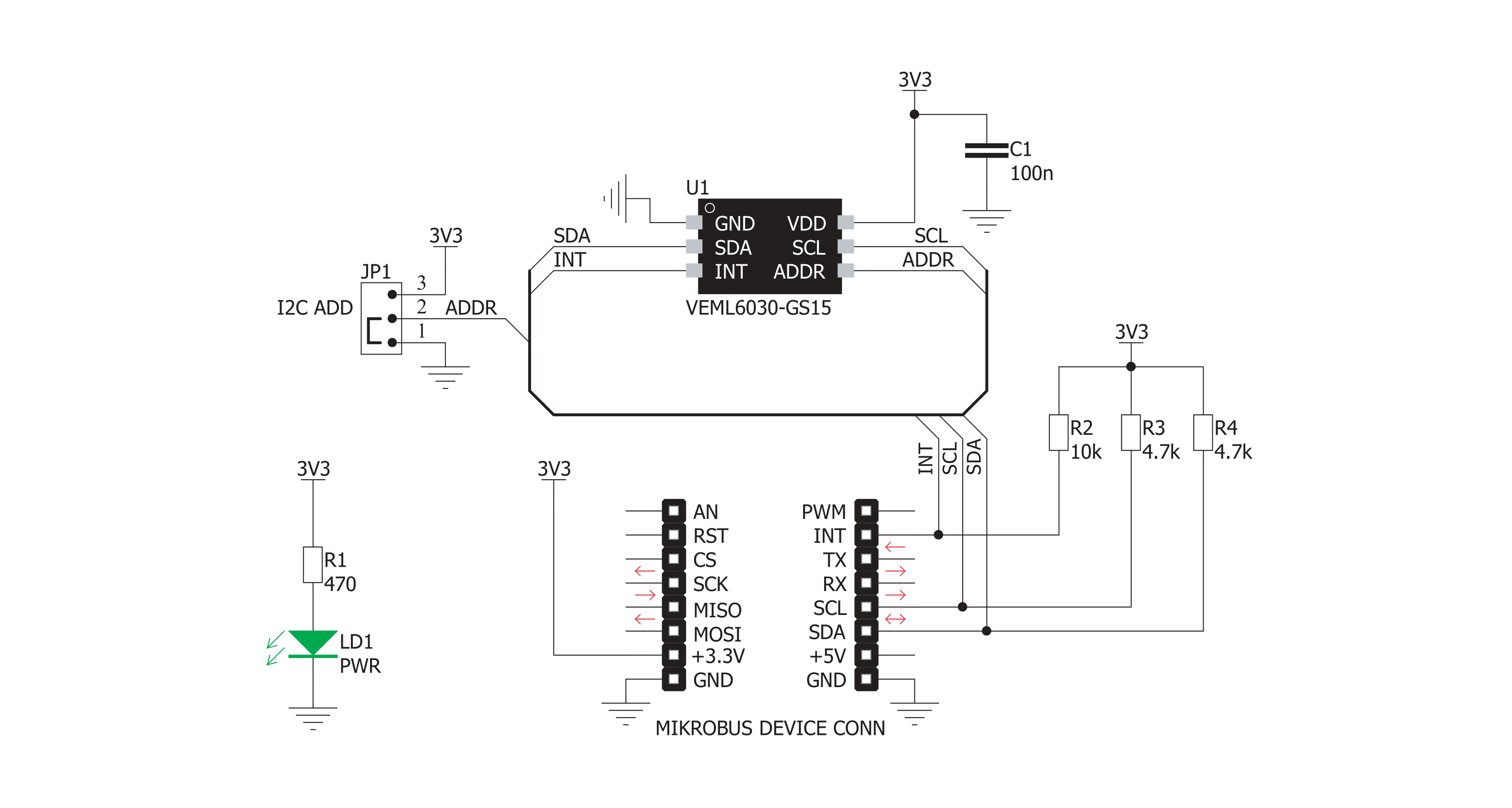
Ambient 5 Click is based on the VEML6030, a high accuracy ambient light sensor (ALS) with I2C interface, from Vishay Semiconductors. This sensor utilizes several proprietary technologies to ensure accurate measurements of the light intensity, with the spectral response very close to a human eye. By utilizing a sensitive photo-diode, low noise amplifier, and a 16-bit A/D converter (ADC), this sensor can provide the data directly, with no need for complex calculations. The dynamic range for the ambient light sensor is very large, starting down from 0 lx up to about 120 klx, with the maximum resolution of only 0.0036 lx/count. The extremely high sensitivity along with the linear response to different light sources, allows this sensor to be placed behind a dark glass or panels made of other semi-transparent materials. The VEML6030 sensor has only six 16-bit registers, which make it very simple to configure and use. Even though, it comes with the mikroSDK compatible library, which simplifies the development even more. However, more detailed
explanation of each command can be found in the datasheet of the VEML6030, if required. A selectable GAIN allows a very wide dynamic range for the ALS measurement. There are two ALS_GAIN bits, allowing the gain level to be set to 1/4x, 1/2x, 1x, and 2x. This offers four different luminosity ranges to be covered for each selected integration time (ALS_IT). For example: the fastest integration time (25ms) results in the lowest resolution (1.8432 lx/count), and combined with the gain of 1/8x, it allows the highest luminosity value to be measured (120,796 lx) Power consumption of the VEML6030 is in tight relation with the programmed integration time, power supply, and amplification. There are two bits available to select the power mode (PSM), four bits to select the integration time (ALS_IT), and two bits to select the gain (ALS_GAIN). These parameters are determining factors for the average power consumption, measurement resolution, and refresh time. By utilizing a such a flexible power saving scheme, the VEML6030 can
be adapted to any type of power sensitive application. A configurable interrupt engine allows optimized firmware to be developed, avoiding polling routines and frequent access over the I2C interface. The interrupt pin (INT) is an open drain output, which is pulled to a HIGH logic level when it is not asserted. When any of the programmed light thresholds is exceeded for a programmed number of times, an interrupt event will be generated, asserting this pin to a LOW logic level. The interrupt pin is routed to the mikroBUS™ INT pin. The slave I2C address of the VEML6030 can be selected by switching the SMD jumper to an appropriate position. Unlike some other devices, this jumper does not set the LSB of the I2C address, but rather selects between two possible values: when tied to GND (0), the I2C address of the VEML6030 will be 0b0010000x. When tied to VCC (1), the I2C address will be 0b1001000x. The x is the I2C address R/W byte. Due to maximum electrical ratings, this Click board™ is to be used with 3.3V MCUs, only.


Features overview
Development board
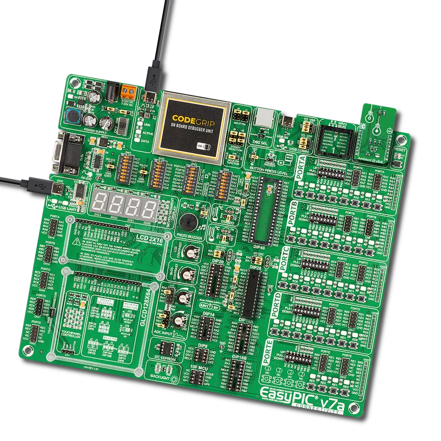
EasyPIC v7a is the seventh generation of PIC development boards specially designed for the needs of rapid development of embedded applications. It supports a wide range of 8-bit PIC microcontrollers from Microchip and has a broad set of unique functions, such as the first-ever embedded debugger/programmer over USB-C. The development board is well organized and designed so that the end-user has all the necessary elements in one place, such as switches, buttons, indicators, connectors, and others. With four different connectors for each port, EasyPIC v7a allows you to connect accessory boards, sensors, and custom electronics more efficiently than ever. Each part of the EasyPIC v7a development board
contains the components necessary for the most efficient operation of the same board. In addition to the advanced integrated CODEGRIP programmer/debugger module, which offers many valuable programming/debugging options and seamless integration with the Mikroe software environment, the board also includes a clean and regulated power supply module for the development board. It can use various external power sources, including an external 12V power supply, 7-23V AC or 9-32V DC via DC connector/screw terminals, and a power source via the USB Type-C (USB-C) connector. Communication options such as USB-UART and RS-232 are also included, alongside the well-
established mikroBUS™ standard, three display options (7-segment, graphical, and character-based LCD), and several different DIP sockets. These sockets cover a wide range of 8-bit PIC MCUs, from PIC10F, PIC12F, PIC16F, PIC16Enh, PIC18F, PIC18FJ, and PIC18FK families. EasyPIC v7a is an integral part of the Mikroe ecosystem for rapid development. Natively supported by Mikroe software tools, it covers many aspects of prototyping and development thanks to a considerable number of different Click boards™ (over a thousand boards), the number of which is growing every day.

Microcontroller Overview
MCU Card / MCU
Architecture
PIC
MCU Memory (KB)
64
Silicon Vendor
Microchip
Pin count
28
RAM (Bytes)
3728
Used MCU Pins
mikroBUS™ mapper
Take a closer look
Click board™ Schematic
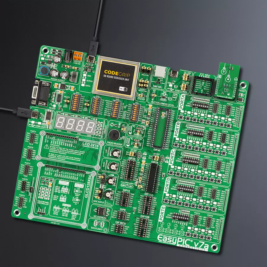
Step by step
Project assembly

Start by selecting your development board and Click board™. Begin with the EasyPIC v7a as your development board.


Track your results in real time
Application Output
1. Application Output - In Debug mode, the 'Application Output' window enables real-time data monitoring, offering direct insight into execution results. Ensure proper data display by configuring the environment correctly using the provided tutorial.

2. UART Terminal - Use the UART Terminal to monitor data transmission via a USB to UART converter, allowing direct communication between the Click board™ and your development system. Configure the baud rate and other serial settings according to your project's requirements to ensure proper functionality. For step-by-step setup instructions, refer to the provided tutorial.

3. Plot Output - The Plot feature offers a powerful way to visualize real-time sensor data, enabling trend analysis, debugging, and comparison of multiple data points. To set it up correctly, follow the provided tutorial, which includes a step-by-step example of using the Plot feature to display Click board™ readings. To use the Plot feature in your code, use the function: plot(*insert_graph_name*, variable_name);. This is a general format, and it is up to the user to replace 'insert_graph_name' with the actual graph name and 'variable_name' with the parameter to be displayed.

Software Support
Library Description
This library contains API for Ambient 5 Click driver.
Key functions:
ambient5_set_register- This function writes the register value to the desired registerambient5_get_register- This function reads data from the desired registerambient5_get_resolution- This function calculates resolution of output data in "high resolution" and "white channel" registers.
Open Source
Code example
The complete application code and a ready-to-use project are available through the NECTO Studio Package Manager for direct installation in the NECTO Studio. The application code can also be found on the MIKROE GitHub account.
/*!
 * \file
 * \brief Ambient5 Click example
 *
 * # Description
 * This application calculates the ambiance light.
 *
 * The demo application is composed of two sections :
 *
 * ## Application Init
 * Initializes i2c driver, powers the device and calculates refresh time.
 *
 * ## Application Task
 * Logs high resolution data after a period of time ( refresh time calculated using - ambient5_getRefreshTime( ) )
 *
 *
 * \author MikroE Team
 *
 */
// ------------------------------------------------------------------- INCLUDES

#include "board.h"
#include "log.h"
#include "ambient5.h"

// ------------------------------------------------------------------ VARIABLES

static ambient5_t ambient5;
static log_t logger;

static uint16_t r_time;
static uint16_t i;
static uint16_t lth;
static uint16_t hth;
static float high_res_light_level;
static float res;

// ------------------------------------------------------ APPLICATION FUNCTIONS

void application_init ( void )
{
    log_cfg_t log_cfg;
    ambient5_cfg_t ambient_cfg;

    /**
     * Logger initialization.
     * Default baud rate: 115200
     * Default log level: LOG_LEVEL_DEBUG
     * @note If USB_UART_RX and USB_UART_TX
     * are defined as HAL_PIN_NC, you will
     * need to define them manually for log to work.
     * See @b LOG_MAP_USB_UART macro definition for detailed explanation.
     */
    LOG_MAP_USB_UART( log_cfg );
    log_init( &logger, &log_cfg );
    log_info( &logger, "---- Application Init ----" );

    //  Click initialization.

    ambient5_cfg_setup( &ambient_cfg );
    AMBIENT5_MAP_MIKROBUS( ambient_cfg, MIKROBUS_1 );
    ambient5_init( &ambient5, &ambient_cfg );
    ambient5_default_cfg( &ambient5 );

	log_printf( &logger, "App init done\r\n" );
}

void application_task ( void )
{
    r_time = ambient5_get_refresh_time( &ambient5 );

    for (i = 0; i < r_time; i++)
	{
		Delay_ms ( 1 );
	}

	high_res_light_level = ambient5_get_high_resolution_light_level( &ambient5 );

	log_printf( &logger, " Ambient Light Level : %.2f lx\r\n", high_res_light_level );

    Delay_ms ( 500 );
}

int main ( void )
{
    /* Do not remove this line or clock might not be set correctly. */
    #ifdef PREINIT_SUPPORTED
    preinit();
    #endif

    application_init( );

    for ( ; ; )
    {
        application_task( );
    }

    return 0;
}

// ------------------------------------------------------------------------ END


