Personalized oxygen tracking with VCNL4020C and PIC18F25K40
Live healthier with daily insights

Published Dec 29, 2023
Click board™
Oximeter 3 Click
Dev. board
EasyPIC v7a
Compiler
NECTO Studio
MCU
PIC18F25K40
Upgrade your solution's health monitoring capabilities with innovative optical pulse oximetry technology
A
A
Hardware Overview
How does it work?
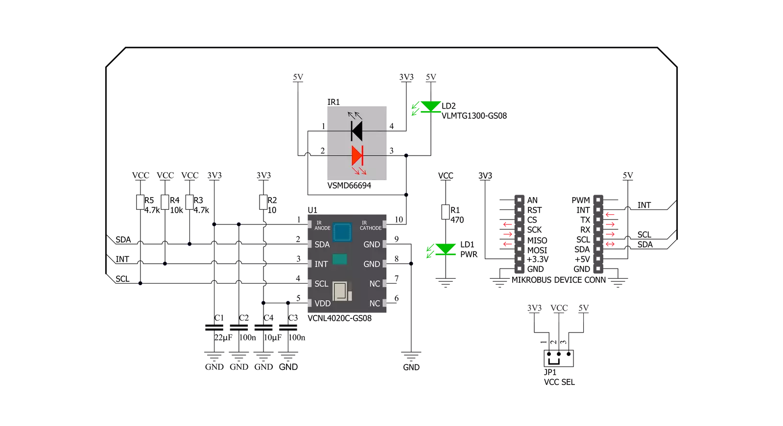
Oximeter 3 Click is based on the VCNL4020C-GS08, a fully integrated biosensor and ambient light sensor with an I2C interface from Vishay Semiconductor. The VCNL4020C-GS08 sensor has a built-in infrared emitter and signal processing IC in a single package with a 16-bit ADC. It also has an ambient light PIN photodiode with close-to-human-eye sensitivity with excellent ambient light suppression through signal modulation. For biosensor functionality, it converts the current from the PIN photodiode to a 16-bit digital data output value, while for ambient light sensing, it converts the current from the ambient light detector, amplifies it, and converts it to a 16-bit digital output stream. The integrated infrared emitter has a peak wavelength of 890nm. It emits light that reflects off an object within 20cm of the sensor and has a programmable drive current from 10mA to 200mA in 10mA steps. The built-in infrared emitter and broader sensitivity
photodiode also can work with the additional onboard green LED and IRLED as designed on this Click board™. As an additional light source, true green color LED (VLMTG1300) with a 525nm peak wavelength is used alongside an infrared dual-color emitting diode (VSMD66694) with 660nm and 940nm peak wavelength well suited for measuring the optical pulse oximetry. The PIN photodiode receives the light reflected off the object and converts it to a current. It has a peak sensitivity of 890nm, matching the peak wavelength of the emitter, and it is insensitive to ambient light. The VCNL4020C also provides ambient light sensing to support conventional backlight and display brightness auto-adjustment. The ambient light sensor receives the visible light and converts it to a current, and it has peak sensitivity at 540nm and bandwidth from 430nm to 610nm. Oximeter 3 Click communicates with the MCU using the standard I2C
2-wire interfacewith a fixed address compatible with all I2C modes (Standard, Fast, and High-Speed). It allows easy access to a biosensor signal and light intensity measurements without complex calculations or programming. It also generates a programmable interrupt signal routed on the INT pin of the mikroBUS™, which offers Wake-Up functionality for the MCU when a proximity event or ambient light change occurs, which reduces processing overhead by eliminating the need for continuous polling. This Click board™ can operate with either 3.3V or 5V logic voltage levels selected via the VCC SEL jumper. This way, both 3.3V and 5V capable MCUs can use the communication lines properly. However, the Click board™ comes equipped with a library containing easy-to-use functions and an example code that can be used, as a reference, for further development.


Features overview
Development board
EasyPIC v7a is the seventh generation of PIC development boards specially designed for the needs of rapid development of embedded applications. It supports a wide range of 8-bit PIC microcontrollers from Microchip and has a broad set of unique functions, such as the first-ever embedded debugger/programmer over USB-C. The development board is well organized and designed so that the end-user has all the necessary elements in one place, such as switches, buttons, indicators, connectors, and others. With four different connectors for each port, EasyPIC v7a allows you to connect accessory boards, sensors, and custom electronics more efficiently than ever. Each part of the EasyPIC v7a development board
contains the components necessary for the most efficient operation of the same board. In addition to the advanced integrated CODEGRIP programmer/debugger module, which offers many valuable programming/debugging options and seamless integration with the Mikroe software environment, the board also includes a clean and regulated power supply module for the development board. It can use various external power sources, including an external 12V power supply, 7-23V AC or 9-32V DC via DC connector/screw terminals, and a power source via the USB Type-C (USB-C) connector. Communication options such as USB-UART and RS-232 are also included, alongside the well-
established mikroBUS™ standard, three display options (7-segment, graphical, and character-based LCD), and several different DIP sockets. These sockets cover a wide range of 8-bit PIC MCUs, from PIC10F, PIC12F, PIC16F, PIC16Enh, PIC18F, PIC18FJ, and PIC18FK families. EasyPIC v7a is an integral part of the Mikroe ecosystem for rapid development. Natively supported by Mikroe software tools, it covers many aspects of prototyping and development thanks to a considerable number of different Click boards™ (over a thousand boards), the number of which is growing every day.

Microcontroller Overview
MCU Card / MCU
Architecture
PIC
MCU Memory (KB)
32
Silicon Vendor
Microchip
Pin count
28
RAM (Bytes)
2048
Used MCU Pins
mikroBUS™ mapper
Take a closer look
Click board™ Schematic
Step by step
Project assembly

Start by selecting your development board and Click board™. Begin with the EasyPIC v7a as your development board.


Software Support
Library Description
This library contains API for Oximeter 3 Click driver.
Key functions:
void oximeter3_generic_write ( uint8_t reg_addr, uint8_t write_data )- Function for writing data to register address.uint8_t oximeter3_generic_read ( uint8_t reg_addr )- Function for reading data from register address.uint16_t oximeter3_read_value ( uint8_t type_macro )- Function for reading value from sensor.
Open Source
Code example
The complete application code and a ready-to-use project are available through the NECTO Studio Package Manager for direct installation in the NECTO Studio. The application code can also be found on the MIKROE GitHub account.
/*!
 * \file
 * \brief Oximeter3 Click example
 *
 * # Description
 * This example demonstrates the use of Oximeter 3 Click board.
 *
 * The demo application is composed of two sections :
 *
 * ## Application Init
 * Initializes the driver, checks the device ID then configures the device for the selected mode.
 *
 * ## Application Task
 * Depending on the selected mode it reads heart rate data (OXIMETER3_HEART_RATE mode) or
 * values of proximity and ambient light sensor (OXIMETER3_PROX or OXIMETER3_ALS modes).
 * All data is being logged on USB UART where you can track their changes.
 *
 * @note
 * In the case of heart rate, please use a Serial Plot application for data plotting.
 *
 * \author MikroE Team
 *
 */
// ------------------------------------------------------------------- INCLUDES

#include "board.h"
#include "log.h"
#include "oximeter3.h"

// ------------------------------------------------------------------ VARIABLES

static oximeter3_t oximeter3;
static log_t logger;

uint8_t dev_mode = 0;
uint16_t rd_val = 0;
uint16_t counter = 2500;

// ------------------------------------------------------ APPLICATION FUNCTIONS

void application_init ( void )
{
    log_cfg_t log_cfg;
    oximeter3_cfg_t cfg;

    uint8_t dev_status;

    /**
     * Logger initialization.
     * Default baud rate: 115200
     * Default log level: LOG_LEVEL_DEBUG
     * @note If USB_UART_RX and USB_UART_TX
     * are defined as HAL_PIN_NC, you will
     * need to define them manually for log to work.
     * See @b LOG_MAP_USB_UART macro definition for detailed explanation.
     */
    LOG_MAP_USB_UART( log_cfg );
    log_init( &logger, &log_cfg );
    log_info( &logger, "---- Application Init ----" );

    //  Click initialization.

    oximeter3_cfg_setup( &cfg );
    OXIMETER3_MAP_MIKROBUS( cfg, MIKROBUS_1 );
    oximeter3_init( &oximeter3, &cfg );

    dev_status = oximeter3_generic_read( &oximeter3, OXIMETER3_REG_PRODUCT_ID );

    if ( dev_status != OXIMETER3_ID_VAL )
    {
        log_printf( &logger, " *****  ERROR!  ***** \r\n" );
        for ( ; ; );
    }

    dev_mode = OXIMETER3_HEART_RATE;

    oximeter3_generic_write( &oximeter3, OXIMETER3_REG_COMMAND,
                                         OXIMETER3_CMD_MEASUREMENT_DISABLE );

    oximeter3_generic_write( &oximeter3, OXIMETER3_REG_INTERRUPT_CTRL,
                                         OXIMETER3_INT_STATUS_PROX );

    if ( OXIMETER3_HEART_RATE == dev_mode )
    {
        oximeter3_generic_write( &oximeter3, OXIMETER3_REG_LED_CURRENT,
                                             OXIMETER3_LED_CURR_MID );
        oximeter3_generic_write( &oximeter3, OXIMETER3_REG_PROX_MODULATOR_TIMING,
                                             OXIMETER3_PROX_TIMING_FREQ_390p625_KHZ );
    }
    else
    {
        oximeter3_generic_write( &oximeter3, OXIMETER3_REG_LED_CURRENT,
                                             OXIMETER3_LED_CURR_MIN );
        oximeter3_generic_write( &oximeter3, OXIMETER3_REG_PROX_MODULATOR_TIMING,
                                             OXIMETER3_PROX_TIMING_FREQ_3p125_MHZ );
    }

    oximeter3_generic_write( &oximeter3, OXIMETER3_REG_PROX_RATE,
                                         OXIMETER3_PROX_RATE_250_MPS );

    oximeter3_generic_write( &oximeter3, OXIMETER3_REG_COMMAND,
                                         OXIMETER3_CMD_MEASUREMENT_ENABLE |
                                         OXIMETER3_CMD_PROX_PERIODIC_MEASUREMENT_ENABLE |
                                         OXIMETER3_CMD_ALS_PERIODIC_MEASUREMENT_ENABLE );

    log_printf( &logger, " ***** APP TASK ***** \r\n" );
}

void application_task ( void )
{
    if ( OXIMETER3_HEART_RATE == dev_mode )
    {
        if( !oximeter3_get_int_status( &oximeter3 ) )
        {
            rd_val = oximeter3_read_value( &oximeter3, OXIMETER3_PROX );
            oximeter3_generic_write( &oximeter3, OXIMETER3_REG_INTERRUPT_STATUS,
                                                 OXIMETER3_INT_STATUS_PROX );

            counter++;
            if ( rd_val > 10000 )
            {
                log_printf( &logger, "%u\r\n", rd_val );
                counter = 2500;
            }
            else if ( counter > 2500 )
            {
                log_printf( &logger, "Please place your index finger on the sensor.\r\n" );
                counter = 0;
            }
        }
    }
    else if ( OXIMETER3_PROX == dev_mode || OXIMETER3_ALS == dev_mode )
    {
        if( !oximeter3_get_int_status( &oximeter3 ) )
        {
            rd_val = oximeter3_read_value( &oximeter3, OXIMETER3_PROX );
            oximeter3_generic_write( &oximeter3, OXIMETER3_REG_INTERRUPT_STATUS,
                                                 OXIMETER3_INT_STATUS_PROX );

            log_printf( &logger, " * Proximity: %u \r\n", rd_val );

            rd_val = oximeter3_read_value( &oximeter3, OXIMETER3_ALS );
            log_printf( &logger, " * ALS: %u \r\n", rd_val );

            log_printf( &logger, "******************** \r\n" );

            Delay_ms ( 500 );
        }
    }
}

int main ( void )
{
    /* Do not remove this line or clock might not be set correctly. */
    #ifdef PREINIT_SUPPORTED
    preinit();
    #endif

    application_init( );

    for ( ; ; )
    {
        application_task( );
    }

    return 0;
}

// ------------------------------------------------------------------------ END


