Assess solar UV intensity with VEML6075 and PIC18F2458 to improve energy conversion efficiency
The future of UV light measurement

Published Nov 01, 2023
Click board™
UV2 Click
Dev. board
EasyPIC v7a
Compiler
NECTO Studio
MCU
PIC18F2458
Dive into the fascinating realm of UV light measurement with our innovative solution, and unlock the potential to safeguard health, optimize processes, and advance scientific discovery
A
A
Hardware Overview
How does it work?
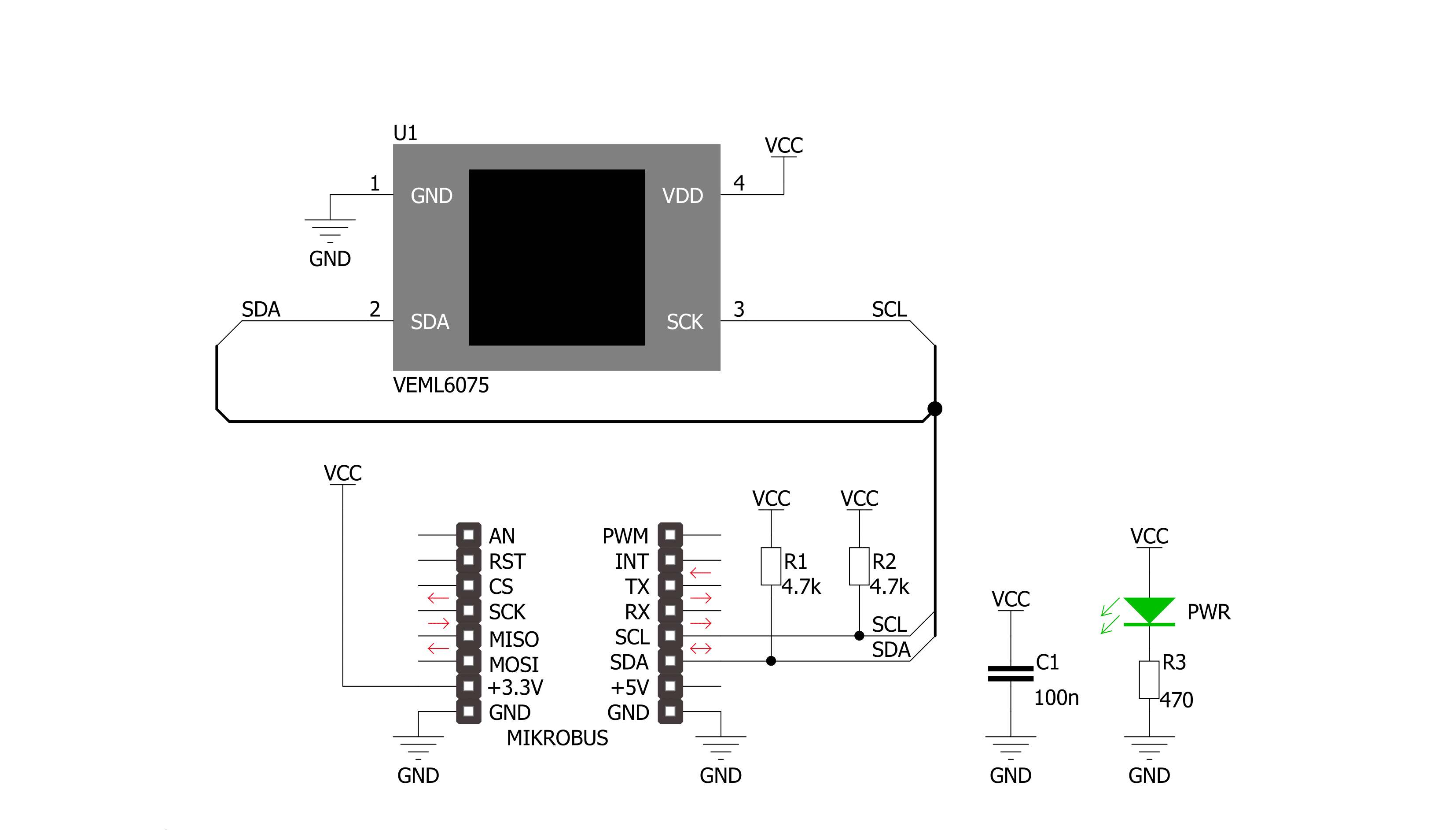
UV2 Click is based on the VEML6075, a UVA and UVB light sensor with an I2C interface from Vishay. The UVA and UVB have their own individual channels, along with the UVD as a dummy channel for dark current cancellation and UVcomp1 and UVcomp2, parts of a normalized spectral response. All those values are essential for deriving the UV radiation values from the sensor readings. The measurement results are stored in separate registers. They remain in registers and can be read from them until the device wakes up and a new measurement is made. The UVB rays
wavelengths ranging from 280nm to 320nm are extremely energetic and harmful for the skin to the extent that they are responsible for 65% of skin tumors. Thankfully, only 0.1% of the solar energy that arrives on the earth’s surface is in the shape of UVB radiation. The UVA ray wavelengths ranging from 320nm to 400nm are less powerful than the previous ones but highly penetrating. They can reach the skin, becoming responsible for photoaging and promoting the onset of different forms of skin cancer. 4.9% of solar energy is made up of UVA rays. The UV2 Click communicates
with the host MCU using an I2C interface over the mikroBUS™ socket, supporting Standard (100KHz) and Fast (400KHz) operating frequencies. This Click board™ can be operated only with a 3.3V logic voltage level. The board must perform appropriate logic voltage level conversion before using MCUs with different logic levels. Also, it comes equipped with a library containing functions and an example code that can be used as a reference for further development.


Features overview
Development board
EasyPIC v7a is the seventh generation of PIC development boards specially designed for the needs of rapid development of embedded applications. It supports a wide range of 8-bit PIC microcontrollers from Microchip and has a broad set of unique functions, such as the first-ever embedded debugger/programmer over USB-C. The development board is well organized and designed so that the end-user has all the necessary elements in one place, such as switches, buttons, indicators, connectors, and others. With four different connectors for each port, EasyPIC v7a allows you to connect accessory boards, sensors, and custom electronics more efficiently than ever. Each part of the EasyPIC v7a development board
contains the components necessary for the most efficient operation of the same board. In addition to the advanced integrated CODEGRIP programmer/debugger module, which offers many valuable programming/debugging options and seamless integration with the Mikroe software environment, the board also includes a clean and regulated power supply module for the development board. It can use various external power sources, including an external 12V power supply, 7-23V AC or 9-32V DC via DC connector/screw terminals, and a power source via the USB Type-C (USB-C) connector. Communication options such as USB-UART and RS-232 are also included, alongside the well-
established mikroBUS™ standard, three display options (7-segment, graphical, and character-based LCD), and several different DIP sockets. These sockets cover a wide range of 8-bit PIC MCUs, from PIC10F, PIC12F, PIC16F, PIC16Enh, PIC18F, PIC18FJ, and PIC18FK families. EasyPIC v7a is an integral part of the Mikroe ecosystem for rapid development. Natively supported by Mikroe software tools, it covers many aspects of prototyping and development thanks to a considerable number of different Click boards™ (over a thousand boards), the number of which is growing every day.

Microcontroller Overview
MCU Card / MCU
Architecture
PIC
MCU Memory (KB)
24
Silicon Vendor
Microchip
Pin count
28
RAM (Bytes)
2048
Used MCU Pins
mikroBUS™ mapper
Take a closer look
Click board™ Schematic
Step by step
Project assembly

Start by selecting your development board and Click board™. Begin with the EasyPIC v7a as your development board.


Track your results in real time
Application Output
1. Application Output - In Debug mode, the 'Application Output' window enables real-time data monitoring, offering direct insight into execution results. Ensure proper data display by configuring the environment correctly using the provided tutorial.

2. UART Terminal - Use the UART Terminal to monitor data transmission via a USB to UART converter, allowing direct communication between the Click board™ and your development system. Configure the baud rate and other serial settings according to your project's requirements to ensure proper functionality. For step-by-step setup instructions, refer to the provided tutorial.

3. Plot Output - The Plot feature offers a powerful way to visualize real-time sensor data, enabling trend analysis, debugging, and comparison of multiple data points. To set it up correctly, follow the provided tutorial, which includes a step-by-step example of using the Plot feature to display Click board™ readings. To use the Plot feature in your code, use the function: plot(*insert_graph_name*, variable_name);. This is a general format, and it is up to the user to replace 'insert_graph_name' with the actual graph name and 'variable_name' with the parameter to be displayed.

Software Support
Library Description
This library contains API for UV2 Click driver.
Key functions:
uv2_set_active_force_mode- This function set active force mode by write force mode UV_AF bit to config register of VEML6075 sesnor on UV 2 Clickuv2_get_uva- This function get UVA data by read UVA register value of VEML6075 sesnor on UV 2 Clickuv2_get_uvb- This function get UVB data by read UVB register value of VEML6075 sesnor on UV 2 Click.
Open Source
Code example
The complete application code and a ready-to-use project are available through the NECTO Studio Package Manager for direct installation in the NECTO Studio. The application code can also be found on the MIKROE GitHub account.
/*!
 * \file
 * \brief UV2 Click example
 *
 * # Description
 * This app measurement UVA and UVB data and calculate UV index level.
 *
 * The demo application is composed of two sections :
 *
 * ## Application Init
 * Initialization device and set default cinfiguration.
 *
 * ## Application Task
 * This is a example which demonstrates the use of UV 2 Click board.
 * UV 2 Click communicates with VEML6075 sesnor via I2C by write to register and read from register.
 * This example measurement UVA and UVB data, calculate UV index level and write log.
 * Results are being sent to the Usart Terminal where you can track their changes.
 * All data logs write on usb uart changes for every 2 sec.
 *
 * \author MikroE Team
 *
 */
// ------------------------------------------------------------------- INCLUDES

#include "board.h"
#include "log.h"
#include "uv2.h"

// ------------------------------------------------------------------ VARIABLES

static uv2_t uv2;
static log_t logger;

// ------------------------------------------------------ APPLICATION FUNCTIONS

void application_init ( void )
{
    log_cfg_t log_cfg;
    uv2_cfg_t cfg;

    uint8_t state_id;

    /**
     * Logger initialization.
     * Default baud rate: 115200
     * Default log level: LOG_LEVEL_DEBUG
     * @note If USB_UART_RX and USB_UART_TX
     * are defined as HAL_PIN_NC, you will
     * need to define them manually for log to work.
     * See @b LOG_MAP_USB_UART macro definition for detailed explanation.
     */
    LOG_MAP_USB_UART( log_cfg );
    log_init( &logger, &log_cfg );
    log_info( &logger, "---- Application Init ----" );

    //  Click initialization.

    uv2_cfg_setup( &cfg );
    UV2_MAP_MIKROBUS( cfg, MIKROBUS_1 );
    uv2_init( &uv2, &cfg );

    Delay_ms ( 100 );

    log_printf( &logger, "------------------------\r\n" );
    log_printf( &logger, "       UV 2  Click      \r\n" );
    log_printf( &logger, "------------------------\r\n" );

    uv2_default_cfg( &uv2 );

    state_id = uv2_check_id( &uv2 );

    if ( state_id )
    {
        log_printf( &logger, "       Configured       \r\n" );
    }
    else
    {
        log_printf( &logger, "         ERROR          \r\n" );
    }

    log_printf( &logger, "------------------------\r\n" );
    Delay_ms ( 100 );
}

void application_task ( void )
{
    uint16_t val_uva;
    uint16_t val_uvb;
    float uv_index;

    val_uva = uv2_get_uva( &uv2 );
    log_printf( &logger, " UVA data = %d \r\n", val_uva );

    val_uvb = uv2_get_uvb( &uv2 );
    log_printf( &logger, " UVB data = %d \r\n", val_uvb );

    uv_index = uv2_get_uv_index( &uv2 );
    log_printf( &logger, " UV Index = %f \r\n", uv_index );

    log_printf( &logger, "------------------------\r\n" );
    Delay_ms ( 1000 );
    Delay_ms ( 1000 );
}

int main ( void )
{
    /* Do not remove this line or clock might not be set correctly. */
    #ifdef PREINIT_SUPPORTED
    preinit();
    #endif

    application_init( );

    for ( ; ; )
    {
        application_task( );
    }

    return 0;
}

// ------------------------------------------------------------------------ END


