Enhance user experiences with advanced ERM motor control based on C1026B002F and PIC18F2685
Sync and thrive!

Published Nov 01, 2023
Click board™
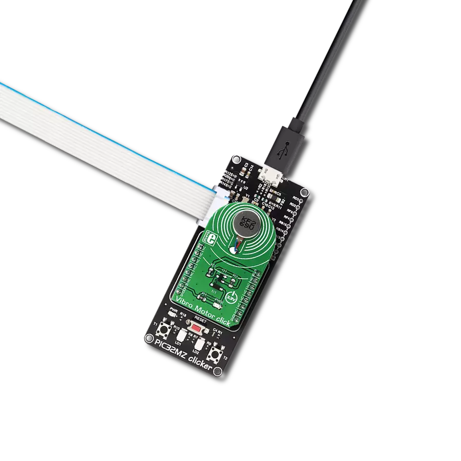
Vibro Motor Click
Dev. board
EasyPIC v7a
Compiler
NECTO Studio
MCU
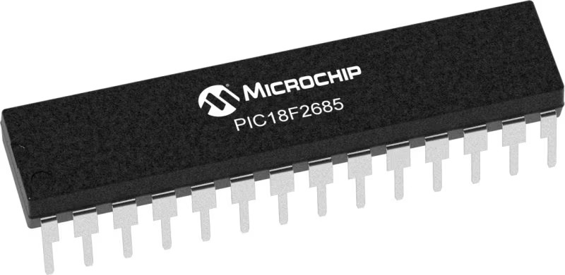
PIC18F2685
In today's dynamic landscape of vibrational applications, our solution aims to simplify motor control and enhance vibrational experiences, offering a user-friendly way to manage ERM motors
A
A
Hardware Overview
How does it work?
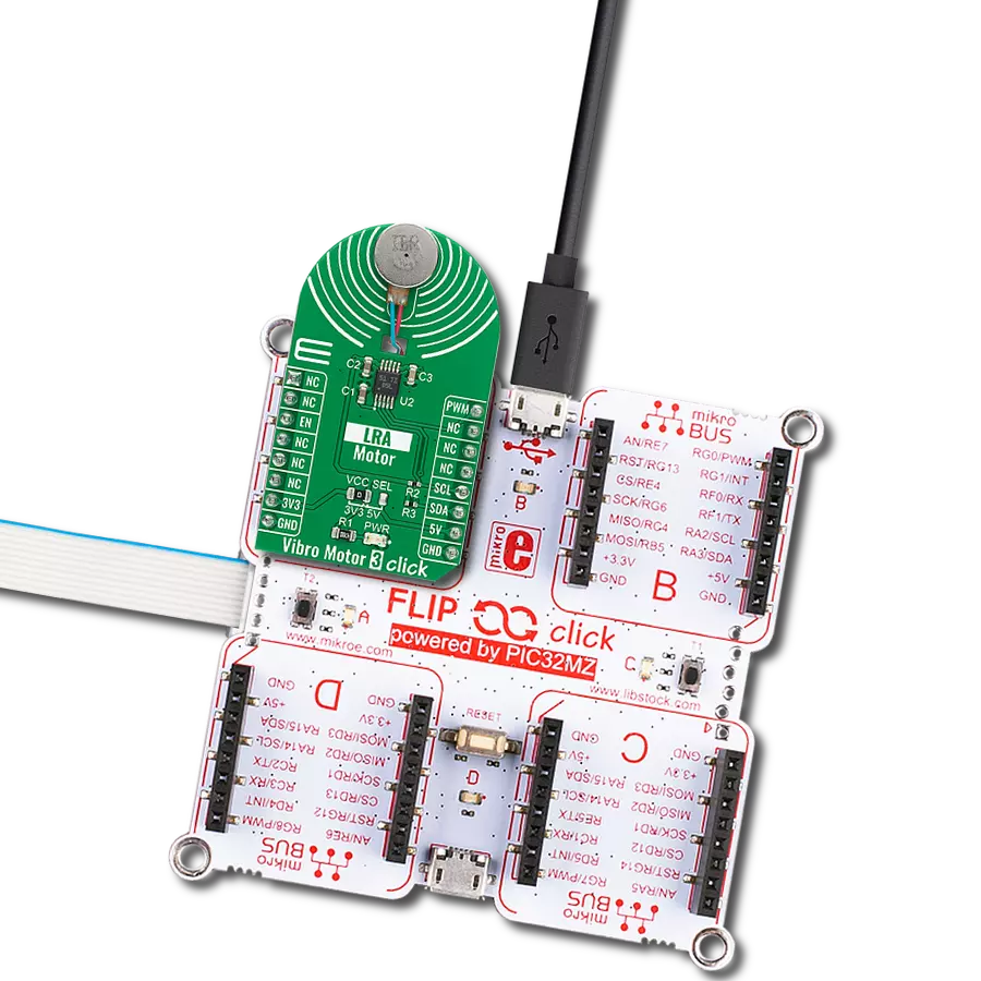
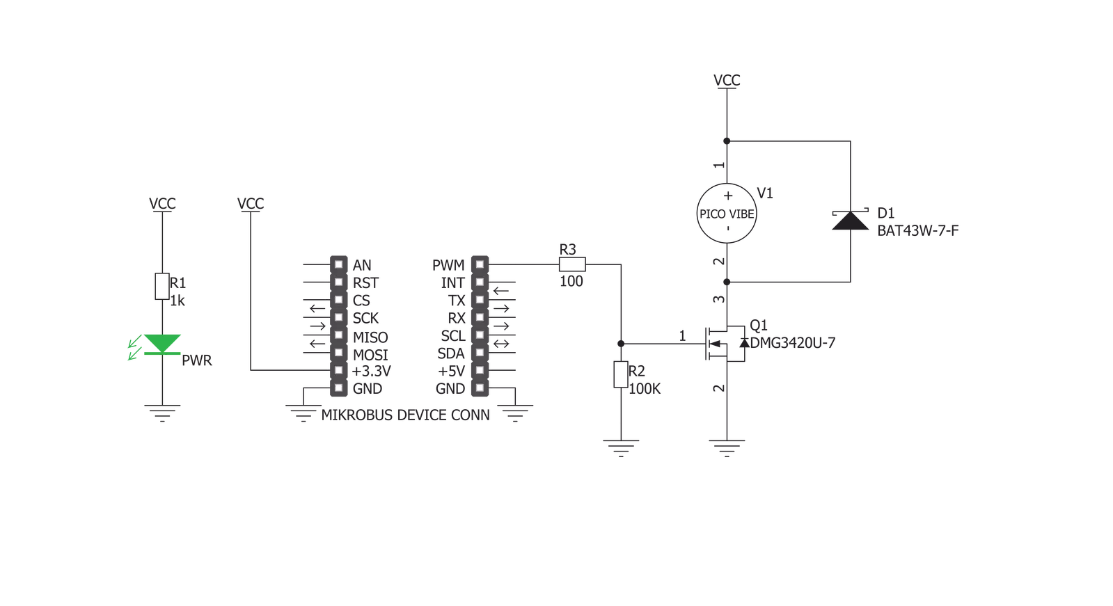
Vibro Motor Click is based on the C1026B002F, a compact-size Eccentric Rotating Mass (ERM) motor. This type of motor is often used for haptic feedback on many small handheld devices, such as cellphones, pagers, RFID scanners, and similar devices. This motor contains a small eccentric weight on its rotor, so it also produces a vibration effect while rotating. This kind of motor is sometimes called a coin motor due to its shape. Besides the vibration motor, the click is also equipped with the DMG3420U, a small MOSFET used to drive the motor. The Vibro Motor click is ideal for adding simple, one-pin-driven haptic feedback on any design. The circuit also contains
a protection diode, which protects the transistor from the reverse voltage since the motor represents an inductive load, and turning off its current can produce a kickback voltage that can damage the transistor. The gate of the MOSFET is driven by the PWM signal, routed through the PWM pin of the mikroBUS™. The PWM signal toggles the gate of the MOSFET with pulses of a certain width. As a result, the current through the motor is varied depending on the pulse width of the PWM signal, which directly affects the speed of the motor, effectively controlling the vibration force that way. The small, eccentric weight attached to the rotor of the coin motor generates
the centrifugal force while it rotates, which in turn results in the wobbling effect of the motor itself. The faster the rotation is, the bigger the force gets. Controlling the motor speed allows for the vibration intensity to be controlled. This Click board™ can be operated only with a 3.3V logic voltage level. The board must perform appropriate logic voltage level conversion before using MCUs with different logic levels. Also, it comes equipped with a library containing functions and an example code that can be used as a reference for further development.


Features overview
Development board
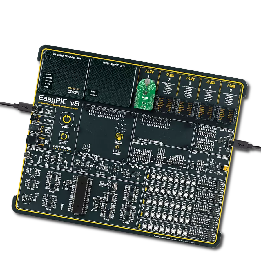
EasyPIC v7a is the seventh generation of PIC development boards specially designed for the needs of rapid development of embedded applications. It supports a wide range of 8-bit PIC microcontrollers from Microchip and has a broad set of unique functions, such as the first-ever embedded debugger/programmer over USB-C. The development board is well organized and designed so that the end-user has all the necessary elements in one place, such as switches, buttons, indicators, connectors, and others. With four different connectors for each port, EasyPIC v7a allows you to connect accessory boards, sensors, and custom electronics more efficiently than ever. Each part of the EasyPIC v7a development board
contains the components necessary for the most efficient operation of the same board. In addition to the advanced integrated CODEGRIP programmer/debugger module, which offers many valuable programming/debugging options and seamless integration with the Mikroe software environment, the board also includes a clean and regulated power supply module for the development board. It can use various external power sources, including an external 12V power supply, 7-23V AC or 9-32V DC via DC connector/screw terminals, and a power source via the USB Type-C (USB-C) connector. Communication options such as USB-UART and RS-232 are also included, alongside the well-
established mikroBUS™ standard, three display options (7-segment, graphical, and character-based LCD), and several different DIP sockets. These sockets cover a wide range of 8-bit PIC MCUs, from PIC10F, PIC12F, PIC16F, PIC16Enh, PIC18F, PIC18FJ, and PIC18FK families. EasyPIC v7a is an integral part of the Mikroe ecosystem for rapid development. Natively supported by Mikroe software tools, it covers many aspects of prototyping and development thanks to a considerable number of different Click boards™ (over a thousand boards), the number of which is growing every day.

Microcontroller Overview
MCU Card / MCU
Architecture
PIC
MCU Memory (KB)
96
Silicon Vendor
Microchip
Pin count
28
RAM (Bytes)
3328
Used MCU Pins
mikroBUS™ mapper
Take a closer look
Click board™ Schematic
Step by step
Project assembly

Start by selecting your development board and Click board™. Begin with the EasyPIC v7a as your development board.


Track your results in real time
Application Output
1. Application Output - In Debug mode, the 'Application Output' window enables real-time data monitoring, offering direct insight into execution results. Ensure proper data display by configuring the environment correctly using the provided tutorial.

2. UART Terminal - Use the UART Terminal to monitor data transmission via a USB to UART converter, allowing direct communication between the Click board™ and your development system. Configure the baud rate and other serial settings according to your project's requirements to ensure proper functionality. For step-by-step setup instructions, refer to the provided tutorial.

3. Plot Output - The Plot feature offers a powerful way to visualize real-time sensor data, enabling trend analysis, debugging, and comparison of multiple data points. To set it up correctly, follow the provided tutorial, which includes a step-by-step example of using the Plot feature to display Click board™ readings. To use the Plot feature in your code, use the function: plot(*insert_graph_name*, variable_name);. This is a general format, and it is up to the user to replace 'insert_graph_name' with the actual graph name and 'variable_name' with the parameter to be displayed.

Software Support
Library Description
This library contains API for Vibro Motor Click driver.
Key functions:
vibromotor_set_duty_cycle- This function sets the PWM duty cycle in percentages ( Range[ 0..1 ] )vibromotor_pwm_stop- This function stops the PWM moudle outputvibromotor_pwm_start- This function starts the PWM moudle output.
Open Source
Code example
The complete application code and a ready-to-use project are available through the NECTO Studio Package Manager for direct installation in the NECTO Studio. The application code can also be found on the MIKROE GitHub account.
/*!
 * @file main.c
 * @brief VibroMotor Click example
 *
 * # Description
 * This application contorl the speed of vibro motor.
 *
 * The demo application is composed of two sections :
 *
 * ## Application Init
 * Initializes GPIO driver and PWM.
 * Configures PWM to 5kHz frequency, calculates maximum duty ratio and starts PWM
 * with duty ratio value 0.
 *
 * ## Application Task
 * Allows user to enter desired command to control
 * Vibro Motor Click board.
 *
 * @author Stefan Ilic
 *
 */

#include "board.h"
#include "log.h"
#include "vibromotor.h"


static vibromotor_t vibromotor;
static log_t logger;

void application_init ( void ) {
    log_cfg_t log_cfg;  /**< Logger config object. */
    vibromotor_cfg_t vibromotor_cfg;  /**< Click config object. */

    /**
     * Logger initialization.
     * Default baud rate: 115200
     * Default log level: LOG_LEVEL_DEBUG
     * @note If USB_UART_RX and USB_UART_TX
     * are defined as HAL_PIN_NC, you will
     * need to define them manually for log to work.
     * See @b LOG_MAP_USB_UART macro definition for detailed explanation.
     */
    LOG_MAP_USB_UART( log_cfg );
    log_init( &logger, &log_cfg );
    log_info( &logger, " Application Init " );

    // Click initialization.

    vibromotor_cfg_setup( &vibromotor_cfg );
    VIBROMOTOR_MAP_MIKROBUS( vibromotor_cfg, MIKROBUS_1 );
    err_t init_flag  = vibromotor_init( &vibromotor, &vibromotor_cfg );
    if ( PWM_ERROR == init_flag ) {
        log_error( &logger, " Application Init Error. " );
        log_info( &logger, " Please, run program again... " );

        for ( ; ; );
    }

    vibromotor_set_duty_cycle ( &vibromotor, 0.0 );
    vibromotor_pwm_start( &vibromotor );

    log_info( &logger, " Application Task " );
}

void application_task ( void ) {
    static int8_t duty_cnt = 1;
    static int8_t duty_inc = 1;
    float duty = duty_cnt / 10.0;

    vibromotor_set_duty_cycle ( &vibromotor, duty );
    log_printf( &logger, "> Duty: %d%%\r\n", ( uint16_t )( duty_cnt * 10 ) );

    Delay_ms ( 500 );

    if ( 10 == duty_cnt ) {
        duty_inc = -1;
    } else if ( 0 == duty_cnt ) {
        duty_inc = 1;
    }
    duty_cnt += duty_inc;
}

int main ( void )
{
    /* Do not remove this line or clock might not be set correctly. */
    #ifdef PREINIT_SUPPORTED
    preinit();
    #endif

    application_init( );

    for ( ; ; )
    {
        application_task( );
    }

    return 0;
}

// ------------------------------------------------------------------------ END