Sense and adapt to various ambient light conditions with VEML3235SL and PIC18LF2455
Brighter, smarter, better

Published Dec 29, 2023
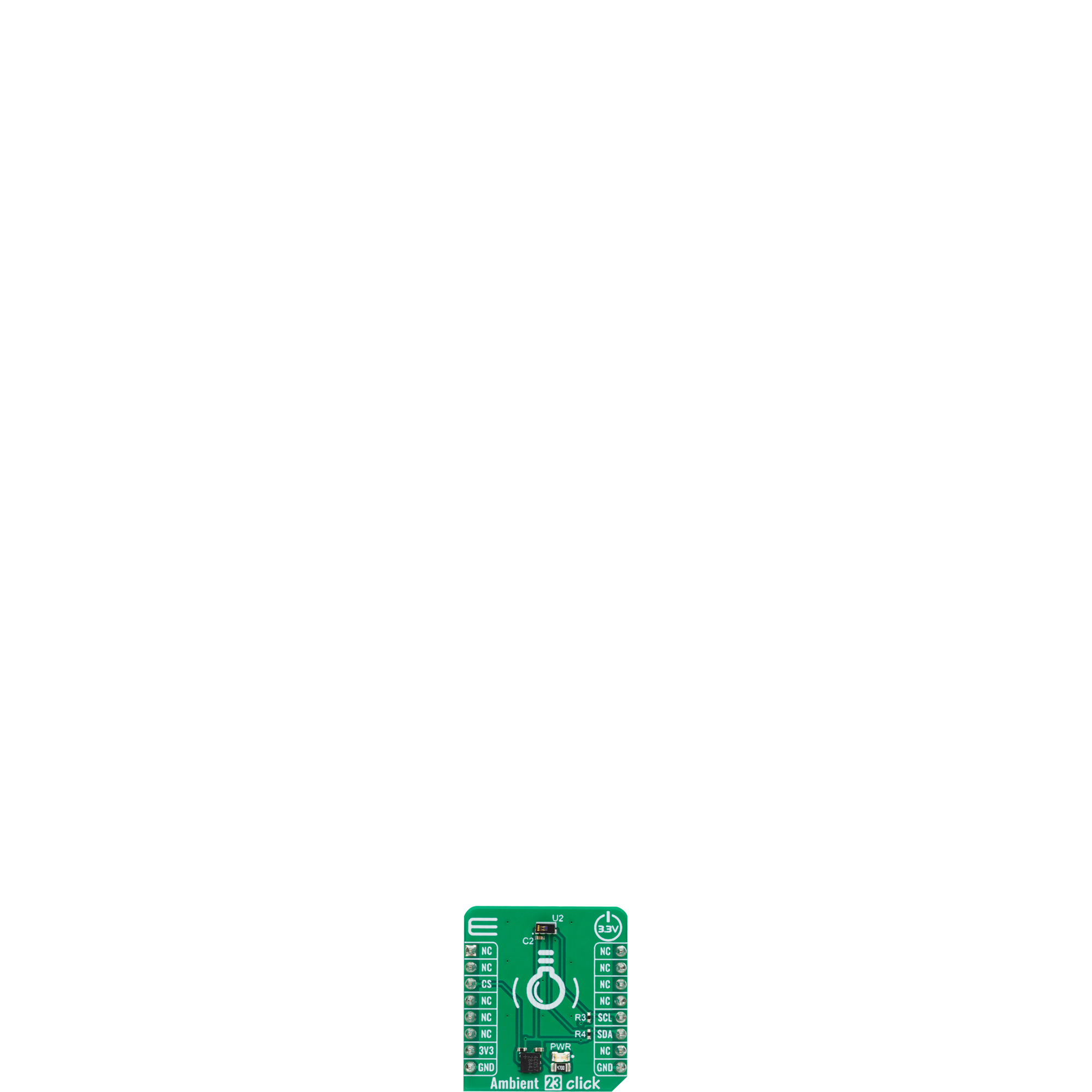
Click board™
Ambient 23 Click
Dev. board
EasyPIC v7
Compiler
NECTO Studio
MCU
PIC18LF2455
Upgrade your lighting control with our cutting-edge technology that measures and optimizes visible ambient light intensity.
A
A
Hardware Overview
How does it work?
Ambient 23 Click is based on the VEML3235SL, a high-accuracy light-to-digital converter from Vishay Semiconductors that transforms light intensity into a digital output signal. The VEML3235SL includes a highly sensitive photodiode, low noise amplifier, and 16-bit A/D converter and supports an easy-to-use serial communication interface. The ambient light read-out is available as a digital value, and the built-in photodiode response is near the human eye's. The 16-bit dynamic range for ambient light detection is from 0.0021 to 17.867lx, with resolution down to 0.0021lx/counts. The sensor's remarkable sensitivity
of 0.0021lx enables it to operate even when placed behind dark cover glass that significantly blocks light. Still, it can also function behind transparent cover glass, as it can handle high illumination levels up to approximately 18klx without saturation. This Click board™ communicates with the host MCU using the standard I2C 2-Wire interface supporting Standard Mode operation with a clock frequency of 100kHz and Fast Mode up to 400kHz. All operations are controlled by the command register, allowing users to easily program the operation setting and latch the light data from VEML3235SL. In addition to its
outstanding temperature compensation capabilities, the VEML3235SL also offers the added benefit of software shutdown mode control, allowing for random measurements, such as once per second, during which the sensor can be switched to shutdown mode to minimize power consumption. This Click board™ can be operated only with a 3.3V logic voltage level. The board must perform appropriate logic voltage level conversion before using MCUs with different logic levels. Also, it comes equipped with a library containing functions and an example code that can be used as a reference for further development.

Features overview
Development board
EasyPIC v7 is the seventh generation of PIC development boards specially designed to develop embedded applications rapidly. It supports a wide range of 8-bit PIC microcontrollers from Microchip and has a broad set of unique functions, such as a powerful onboard mikroProg programmer and In-Circuit debugger over USB-B. The development board is well organized and designed so that the end-user has all the necessary elements in one place, such as switches, buttons, indicators, connectors, and others. With four different connectors for each port, EasyPIC v7 allows you to connect accessory boards, sensors, and custom electronics more efficiently than ever. Each part of
the EasyPIC v7 development board contains the components necessary for the most efficient operation of the same board. An integrated mikroProg, a fast USB 2.0 programmer with mikroICD hardware In-Circuit Debugger, offers many valuable programming/debugging options and seamless integration with the Mikroe software environment. Besides it also includes a clean and regulated power supply block for the development board. It can use various external power sources, including an external 12V power supply, 7-23V AC or 9-32V DC via DC connector/screw terminals, and a power source via the USB Type-B (USB-B) connector. Communication options such as
USB-UART and RS-232 are also included, alongside the well-established mikroBUS™ standard, three display options (7-segment, graphical, and character-based LCD), and several different DIP sockets. These sockets cover a wide range of 8-bit PIC MCUs, from PIC10F, PIC12F, PIC16F, PIC16Enh, PIC18F, PIC18FJ, and PIC18FK families. EasyPIC v7 is an integral part of the Mikroe ecosystem for rapid development. Natively supported by Mikroe software tools, it covers many aspects of prototyping and development thanks to a considerable number of different Click boards™ (over a thousand boards), the number of which is growing every day.

Microcontroller Overview
MCU Card / MCU
Architecture
PIC
MCU Memory (KB)
24
Silicon Vendor
Microchip
Pin count
28
RAM (Bytes)
2048
Used MCU Pins
mikroBUS™ mapper
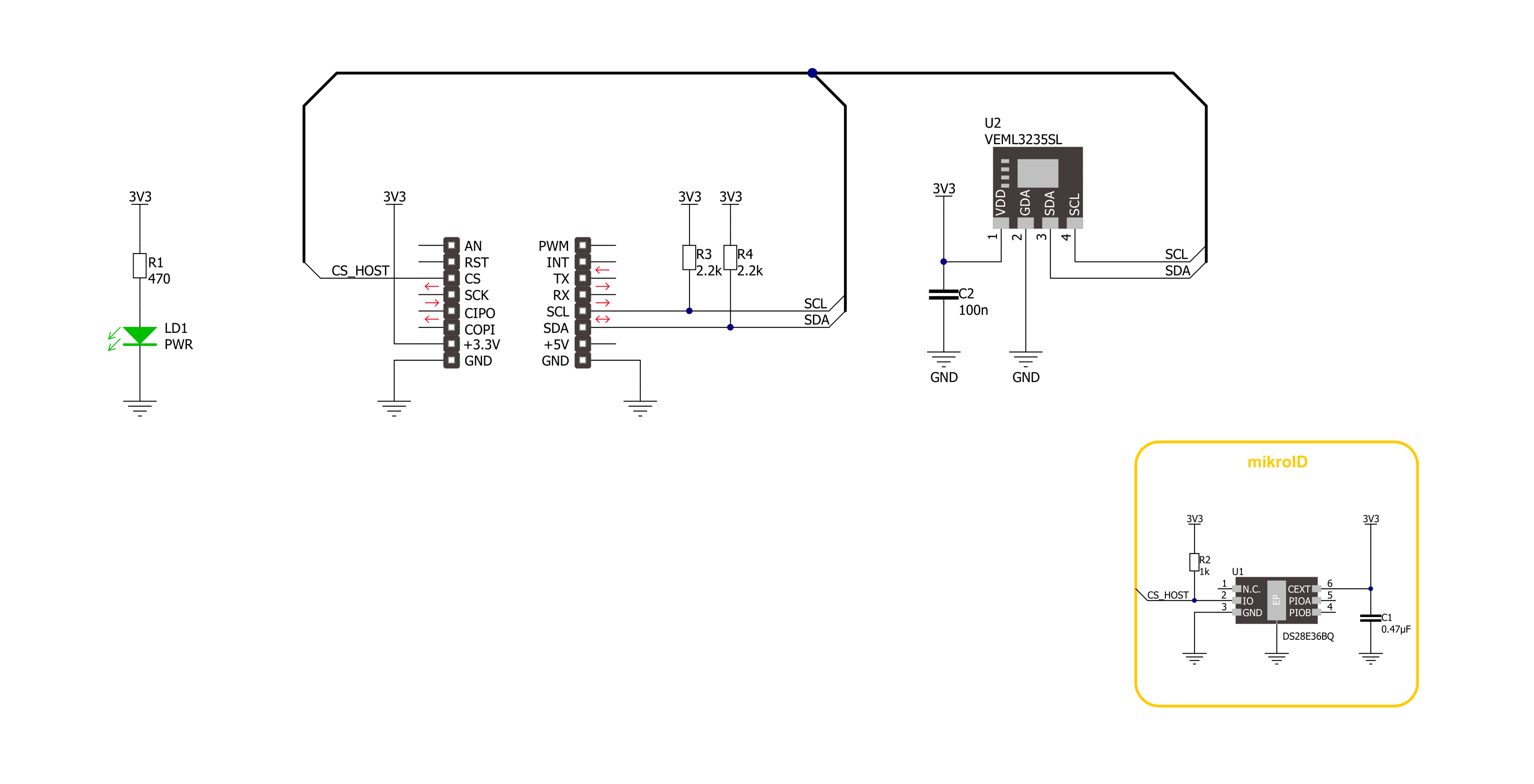
Take a closer look
Click board™ Schematic
Step by step
Project assembly

Start by selecting your development board and Click board™. Begin with the EasyPIC v7 as your development board.


Track your results in real time
Application Output
1. Application Output - In Debug mode, the 'Application Output' window enables real-time data monitoring, offering direct insight into execution results. Ensure proper data display by configuring the environment correctly using the provided tutorial.

2. UART Terminal - Use the UART Terminal to monitor data transmission via a USB to UART converter, allowing direct communication between the Click board™ and your development system. Configure the baud rate and other serial settings according to your project's requirements to ensure proper functionality. For step-by-step setup instructions, refer to the provided tutorial.

3. Plot Output - The Plot feature offers a powerful way to visualize real-time sensor data, enabling trend analysis, debugging, and comparison of multiple data points. To set it up correctly, follow the provided tutorial, which includes a step-by-step example of using the Plot feature to display Click board™ readings. To use the Plot feature in your code, use the function: plot(*insert_graph_name*, variable_name);. This is a general format, and it is up to the user to replace 'insert_graph_name' with the actual graph name and 'variable_name' with the parameter to be displayed.

Software Support
Library Description
This library contains API for Ambient 23 Click driver.
Key functions:
ambient23_reg_read- Ambient 23 register reading function.ambient23_calculate_res- Ambient 23 get conversion data function.ambient23_read_light_data- Ambient 23 get light data function.
Open Source
Code example
The complete application code and a ready-to-use project are available through the NECTO Studio Package Manager for direct installation in the NECTO Studio. The application code can also be found on the MIKROE GitHub account.
/*!
 * @file main.c
 * @brief Ambient 23 Click example
 *
 * # Description
 * This example demonstrates the use of Ambient 23 Click board by measuring
 * the ambient light level in Lux.
 *
 * The demo application is composed of two sections :
 *
 * ## Application Init
 * Initializes the driver, checks communication by reading part ID
 * and performs the Click default configuration.
 *
 * ## Application Task
 * Measuring ambient light level by reading data from the Ambient 23 Click board
 * and displaying it using UART Serial terminal.
 *
 * @author Stefan Ilic
 *
 */

#include "board.h"
#include "log.h"
#include "ambient23.h"

static ambient23_t ambient23;
static log_t logger;

void application_init ( void )
{
    log_cfg_t log_cfg;  /**< Logger config object. */
    ambient23_cfg_t ambient23_cfg;  /**< Click config object. */

    /**
     * Logger initialization.
     * Default baud rate: 115200
     * Default log level: LOG_LEVEL_DEBUG
     * @note If USB_UART_RX and USB_UART_TX
     * are defined as HAL_PIN_NC, you will
     * need to define them manually for log to work.
     * See @b LOG_MAP_USB_UART macro definition for detailed explanation.
     */
    LOG_MAP_USB_UART( log_cfg );
    log_init( &logger, &log_cfg );
    log_info( &logger, " Application Init " );

    // Click initialization.
    ambient23_cfg_setup( &ambient23_cfg );
    AMBIENT23_MAP_MIKROBUS( ambient23_cfg, MIKROBUS_1 );
    if ( I2C_MASTER_ERROR == ambient23_init( &ambient23, &ambient23_cfg ) )
    {
        log_error( &logger, " Communication init." );
        for ( ; ; );
    }

    uint16_t part_id = 0;
    ambient23_reg_read( &ambient23, AMBIENT23_REG_DEVICE_ID, &part_id );
    if ( AMBIENT23_PART_ID != ( uint8_t ) part_id )
    {
        log_error( &logger, " Communication error." );
        for ( ; ; );
    }

    if ( AMBIENT23_ERROR == ambient23_default_cfg ( &ambient23 ) )
    {
        log_error( &logger, " Default configuration." );
        for ( ; ; );
    }

    log_info( &logger, " Application Task " );
}

void application_task ( void )
{
    float data_tmp;

    ambient23_read_light_data( &ambient23, &data_tmp );
    log_printf( &logger, "Data: %.2f lux\r\n", data_tmp );
    Delay_ms ( 1000 );
}

int main ( void )
{
    /* Do not remove this line or clock might not be set correctly. */
    #ifdef PREINIT_SUPPORTED
    preinit();
    #endif

    application_init( );

    for ( ; ; )
    {
        application_task( );
    }

    return 0;
}

// ------------------------------------------------------------------------ END


