Experience the voltage step-down elegance with BMR4613001/001 and PIC18LF25K40
Synchronous step-down beast!
Published Dec 29, 2023
Click board™
Buck 14 Click
Dev. board
EasyPIC v7
Compiler
NECTO Studio
MCU
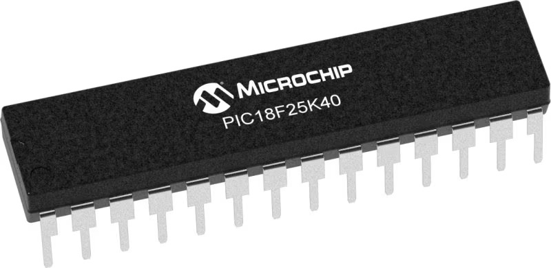
PIC18LF25K40
Through its ability to step down voltages with exceptional efficiency, our buck converter also contributes to a greener and more sustainable future by conserving energy resources
A
A
Hardware Overview
How does it work?
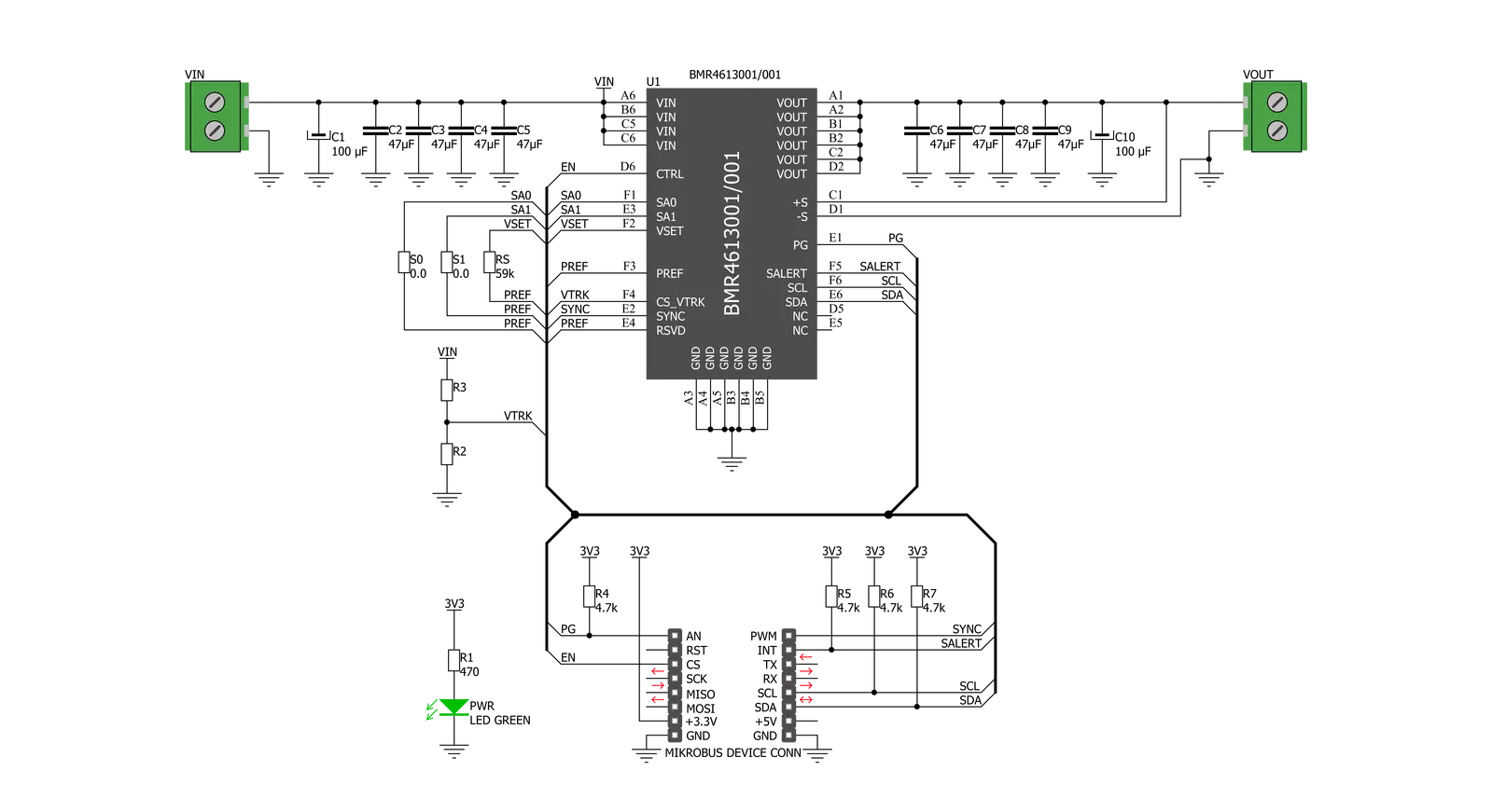
Buck 14 Click is based on the BMR4613001/001 - a PoL regulator from Flex that incorporates a wide range of readable and configurable power management features that are simple to implement with a minimum of external components. Additionally, it includes protection features that continuously safeguard the load from damage due to unexpected system faults. A fault is also shown as an alert on the ALR pin of the mikroBUS™ socket. The product is delivered with a default configuration suitable for various operations regarding input voltage, output voltage, and load. The configuration is stored in an internal Non-Volatile Memory (NVM). All power management functions can be reconfigured using the PMBus interface. It is possible to monitor various parameters through the PMBus interface. Fault conditions can be monitored using the
ALERT pin, which will be asserted when any pre-configured fault or warning conditions occur. The Buck 14 click supports tracking the output from a master voltage applied to the VTRK pin of BMR4613001/001. To select the tracking mode, a resistance ≤ 4.22 kΩ must be connected between the VSET and PREF pins (RS resistor). The tracking ratio is controlled by an internal feedback divider RDIV and an external resistive voltage divider (R3, R2, not populated on the board) placed from the supply being tracked to GND pins. Unlike PID-based digital power regulators, the product uses a state-space model-based algorithm valid for both the small- and large-signal response and accounts for duty-cycle saturation effects. This eliminates the need for users to determine and set thresholds for transitioning from linear to nonlinear modes. These capabilities result in a fast loop transient
response and the possibility of reducing the number of output capacitors. The product features a remote control input through the EN pin and a PMBus enable function by the command OPERATION to control the output voltage. It is also possible to configure the output to be always on. By default, the output is controlled by the EN pin only. The output voltage control can be reconfigured using the PMBus command ON_OFF_CONFIG. It is designed to operate in different thermal environments, and sufficient cooling must ensure reliable operation. Cooling is achieved mainly by conduction, from the pins to the host board, and convection, which depends on the product's airflow. Increased airflow enhances the cooling of the product.

Features overview
Development board
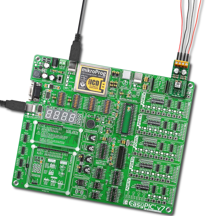
EasyPIC v7 is the seventh generation of PIC development boards specially designed to develop embedded applications rapidly. It supports a wide range of 8-bit PIC microcontrollers from Microchip and has a broad set of unique functions, such as a powerful onboard mikroProg programmer and In-Circuit debugger over USB-B. The development board is well organized and designed so that the end-user has all the necessary elements in one place, such as switches, buttons, indicators, connectors, and others. With four different connectors for each port, EasyPIC v7 allows you to connect accessory boards, sensors, and custom electronics more efficiently than ever. Each part of
the EasyPIC v7 development board contains the components necessary for the most efficient operation of the same board. An integrated mikroProg, a fast USB 2.0 programmer with mikroICD hardware In-Circuit Debugger, offers many valuable programming/debugging options and seamless integration with the Mikroe software environment. Besides it also includes a clean and regulated power supply block for the development board. It can use various external power sources, including an external 12V power supply, 7-23V AC or 9-32V DC via DC connector/screw terminals, and a power source via the USB Type-B (USB-B) connector. Communication options such as
USB-UART and RS-232 are also included, alongside the well-established mikroBUS™ standard, three display options (7-segment, graphical, and character-based LCD), and several different DIP sockets. These sockets cover a wide range of 8-bit PIC MCUs, from PIC10F, PIC12F, PIC16F, PIC16Enh, PIC18F, PIC18FJ, and PIC18FK families. EasyPIC v7 is an integral part of the Mikroe ecosystem for rapid development. Natively supported by Mikroe software tools, it covers many aspects of prototyping and development thanks to a considerable number of different Click boards™ (over a thousand boards), the number of which is growing every day.

Microcontroller Overview
MCU Card / MCU
Architecture
PIC
MCU Memory (KB)
32
Silicon Vendor
Microchip
Pin count
28
RAM (Bytes)
2048
Used MCU Pins
mikroBUS™ mapper
Take a closer look
Click board™ Schematic
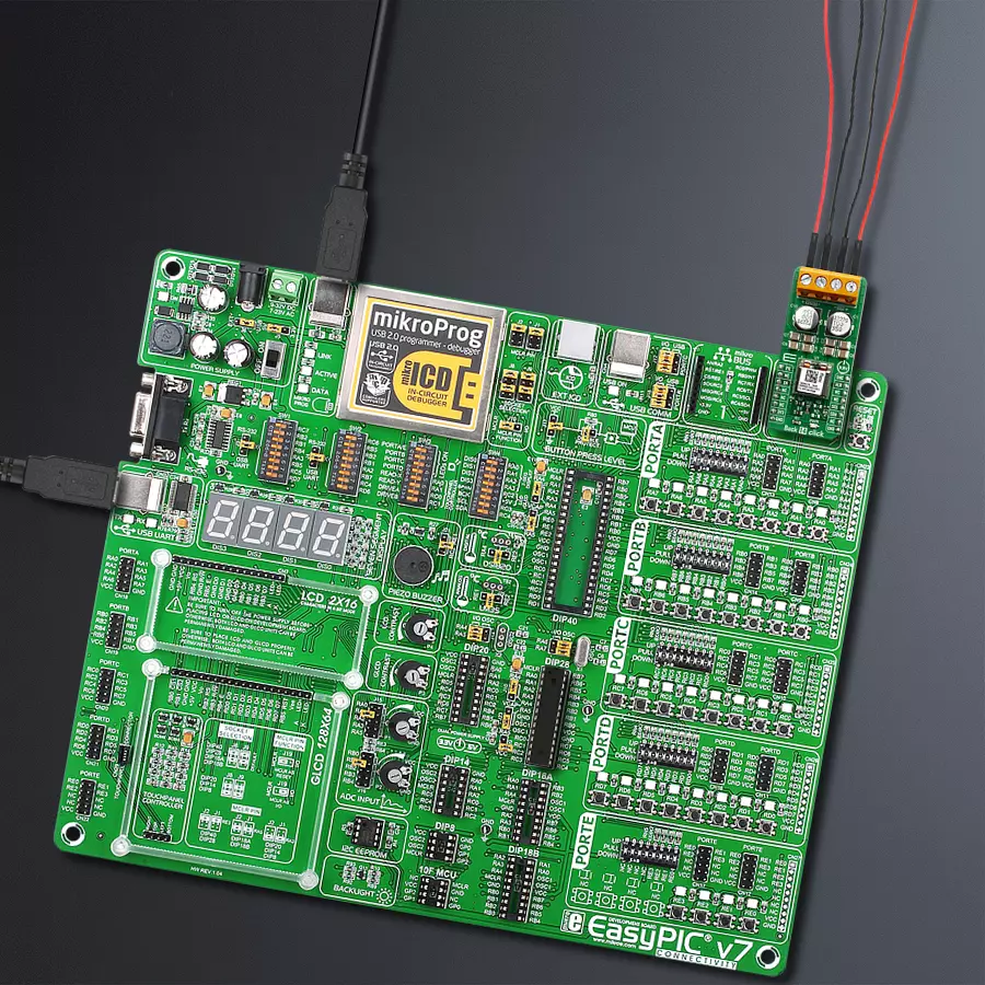
Step by step
Project assembly

Start by selecting your development board and Click board™. Begin with the EasyPIC v7 as your development board.


Software Support
Library Description
This library contains API for Buck 14 Click driver.
Key functions:
buck14_power_ctrl- This function sets state of the power control pinbuck14_salert- This function gets manufacturer IDbuc14_write_vout- This function sets output voltage
Open Source
Code example
The complete application code and a ready-to-use project are available through the NECTO Studio Package Manager for direct installation in the NECTO Studio. The application code can also be found on the MIKROE GitHub account.
/*!
 * \file
 * \brief Buck14 Click example
 *
 * # Description
 * This app enables usage of high-efficiency step-down converter.
 *
 * The demo application is composed of two sections :
 *
 * ## Application Init
 * Configure device.
 *
 * ## Application Task
 * Sends 4 different commands for VOUT in span of 8sec
 *
 * *note:*
 * When you send data you should send LSB first.
 * Device input V should be beetween 4.5 - 14 V.
 * Device output V could be from 0.5 - 5 V deepending from limits you set currently it is set to 1V.
 *
 * \author MikroE Team
 *
 */
// ------------------------------------------------------------------- INCLUDES

#include "board.h"
#include "log.h"
#include "buck14.h"

// ------------------------------------------------------------------ VARIABLES

static buck14_t buck14;
static log_t logger;

// ------------------------------------------------------- ADDITIONAL FUNCTIONS

void error_handler ( uint8_t stat_data )
{
    if ( stat_data == BUCK14_ERROR )
    {
        log_printf( &logger, "ERROR! \r\n " );
        for ( ; ; );
    }
    else if ( stat_data == BUCK14_ID_ERROR )
    {
        log_printf( &logger, "ID ERROR! \r\n " );
        for ( ; ; );
    }
    else if ( stat_data == BUCK14_CMD_ERROR )
    {
        log_printf( &logger, "CMD ERROR! \r\n " );
    }
}

void read_vout_data ( buck14_t *ctx )
{
    uint16_t temp_data;

    temp_data = buc14_read_vout( &buck14 );
    log_printf( &logger, "VOUT ~ %u mV \r\n", temp_data );
}

// ------------------------------------------------------ APPLICATION FUNCTIONS

void application_init ( void )
{
    log_cfg_t log_cfg;
    buck14_cfg_t cfg;
    uint8_t write_data;
    uint8_t status_data;

    /**
     * Logger initialization.
     * Default baud rate: 115200
     * Default log level: LOG_LEVEL_DEBUG
     * @note If USB_UART_RX and USB_UART_TX
     * are defined as HAL_PIN_NC, you will
     * need to define them manually for log to work.
     * See @b LOG_MAP_USB_UART macro definition for detailed explanation.
     */
    LOG_MAP_USB_UART( log_cfg );
    log_init( &logger, &log_cfg );
    log_info( &logger, "---- Application Init ----" );

    //  Click initialization.

    buck14_cfg_setup( &cfg );
    BUCK14_MAP_MIKROBUS( cfg, MIKROBUS_1 );
    buck14_init( &buck14, &cfg );

    buck14_reset( &buck14 );

    write_data  = BUCK14_CTRL_ENABLE_NO_MARGIN;
    buck14_generic_write( &buck14, BUCK14_CMD_OPERATION, &write_data , 1 );
    Delay_ms ( 300 );

    status_data = buck14_check_mfr_id(  &buck14 );
    error_handler( status_data );
    log_printf( &logger, "-Device ID OK!\r\n" );

    buck14_power_ctrl( &buck14, BUCK14_PIN_STATE_HIGH );

    buck14_default_cfg( &buck14 );
    log_printf( &logger, " ***** App init ***** \r\n" );
    log_printf( &logger, "----------------------\r\n" );
    Delay_ms ( 100 );
}

void application_task ( void )
{
    uint8_t status_data;
    float vout_value;

    vout_value = 1.2;
    status_data = buc14_write_vout( &buck14, vout_value );
    error_handler( status_data );

    if ( status_data == BUCK14_SUCCESSFUL )
    {
        read_vout_data(  &buck14 );
    }
    // 8 seconds delay
    Delay_ms ( 1000 );
    Delay_ms ( 1000 );
    Delay_ms ( 1000 );
    Delay_ms ( 1000 );
    Delay_ms ( 1000 );
    Delay_ms ( 1000 );
    Delay_ms ( 1000 );
    Delay_ms ( 1000 );

    vout_value = 3.7;
    status_data = buc14_write_vout( &buck14, vout_value );
    error_handler( status_data );

    if ( status_data == BUCK14_SUCCESSFUL )
    {
        read_vout_data( &buck14 );
    }

    // 8 seconds delay
    Delay_ms ( 1000 );
    Delay_ms ( 1000 );
    Delay_ms ( 1000 );
    Delay_ms ( 1000 );
    Delay_ms ( 1000 );
    Delay_ms ( 1000 );
    Delay_ms ( 1000 );
    Delay_ms ( 1000 );

    vout_value = 2.5;
    status_data = buc14_write_vout( &buck14, vout_value );
    error_handler( status_data );

    if ( status_data == BUCK14_SUCCESSFUL )
    {
        read_vout_data(  &buck14 );
    }

    // 8 seconds delay
    Delay_ms ( 1000 );
    Delay_ms ( 1000 );
    Delay_ms ( 1000 );
    Delay_ms ( 1000 );
    Delay_ms ( 1000 );
    Delay_ms ( 1000 );
    Delay_ms ( 1000 );
    Delay_ms ( 1000 );

    vout_value = 4.5;
    status_data = buc14_write_vout(  &buck14, vout_value );
    error_handler( status_data );

    if ( status_data == BUCK14_SUCCESSFUL )
    {
        read_vout_data(  &buck14 );
    }

    Delay_ms ( 1000 );
    Delay_ms ( 1000 );
    Delay_ms ( 1000 );
    Delay_ms ( 1000 );
    log_printf( &logger, "```````````````\r\n" );
    Delay_ms ( 1000 );
    Delay_ms ( 1000 );
    Delay_ms ( 1000 );
    Delay_ms ( 1000 );
}

int main ( void )
{
    /* Do not remove this line or clock might not be set correctly. */
    #ifdef PREINIT_SUPPORTED
    preinit();
    #endif

    application_init( );

    for ( ; ; )
    {
        application_task( );
    }

    return 0;
}

// ------------------------------------------------------------------------ END


