Accurately measure and analyze the magnitude of earthquakes with D7S and PIC18F25J50
Measuring Earth's fury
Published Nov 01, 2023
Click board™
Earthquake click
Dev. board
EasyPIC v7
Compiler
NECTO Studio
MCU
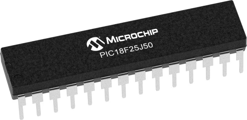
PIC18F25J50
This solution provides crucial data that aids in understanding and quantifying the seismic activity of our planet
A
A
Hardware Overview
How does it work?
Earthquake Click is based on the D7S, the world’s smallest class-size high-precision seismic sensor from Omron. It uses the SI (spectral intensity) value, which has a high correlation with the seismic intensity scale that indicates the magnitude of an earthquake and provides higher-precision judgment of seismic intensity scales. When an earthquake occurs with a seismic intensity equivalent to 5 Upper or higher on the JMA (Japan Meteorological Agency) Seismic Intensity Scale, the D7S will activate the shutoff output to notify the user of an earthquake. JMA, or
Japan Meteorological Agency Intensity Scale, is used in Japan and Taiwan to measure the intensity of earthquakes. The scale goes from 0 to 7. Level 5 on this scale indicates when objects inside a house start falling, like books from the shelf, dishes in a cupboard, cracks formed on walls, and more. Earthquake Click uses a standard 2-Wire I2C interface to communicate with the host MCU. The shutoff terminal on IN1 will go active (ON) when the shutoff judgment condition and collapse detection condition are met. The processing notification output IN2 will go active (ON) during
the earthquake calculations, offset acquisition, and self-diagnostic processing. The initial setting input ST changes the sensor from Normal mode to Initial Installation mode for input from an external device. This Click board™ can operate with either 3.3V or 5V logic voltage levels selected via the 3.3V 5V jumper. This way, both 3.3V and 5V capable MCUs can use the communication lines properly. However, the Click board™ comes equipped with a library containing easy-to-use functions and an example code that can be used as a reference for further development.


Features overview
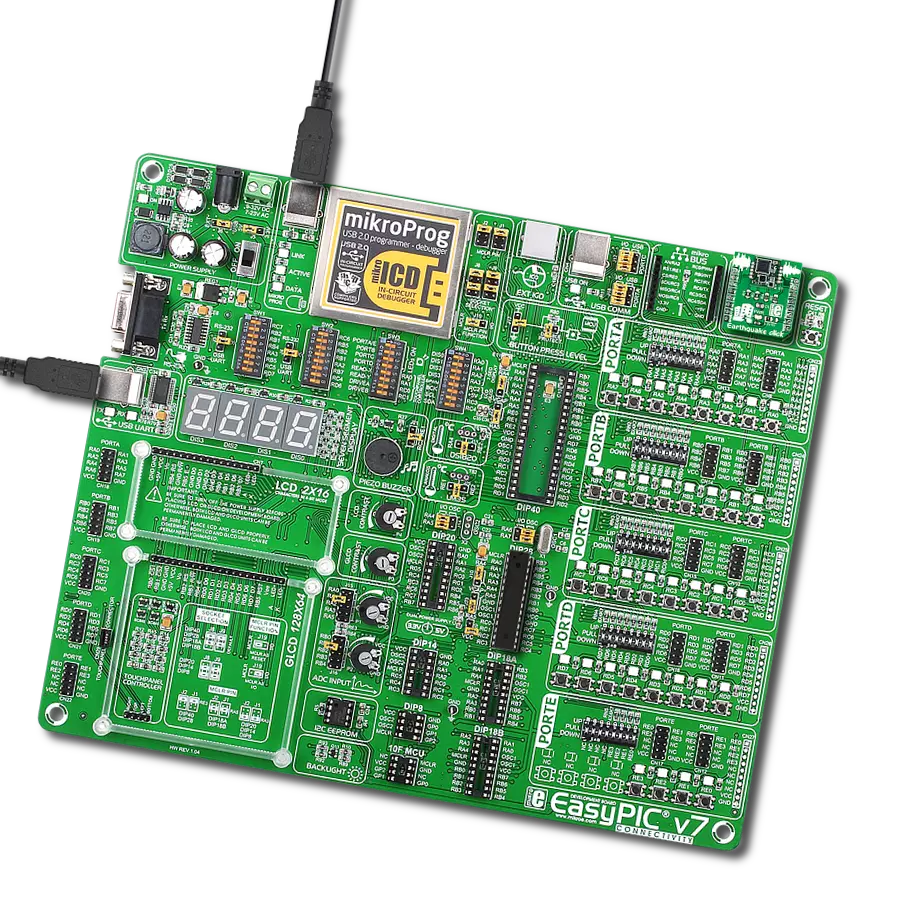
Development board
EasyPIC v7 is the seventh generation of PIC development boards specially designed to develop embedded applications rapidly. It supports a wide range of 8-bit PIC microcontrollers from Microchip and has a broad set of unique functions, such as a powerful onboard mikroProg programmer and In-Circuit debugger over USB-B. The development board is well organized and designed so that the end-user has all the necessary elements in one place, such as switches, buttons, indicators, connectors, and others. With four different connectors for each port, EasyPIC v7 allows you to connect accessory boards, sensors, and custom electronics more efficiently than ever. Each part of
the EasyPIC v7 development board contains the components necessary for the most efficient operation of the same board. An integrated mikroProg, a fast USB 2.0 programmer with mikroICD hardware In-Circuit Debugger, offers many valuable programming/debugging options and seamless integration with the Mikroe software environment. Besides it also includes a clean and regulated power supply block for the development board. It can use various external power sources, including an external 12V power supply, 7-23V AC or 9-32V DC via DC connector/screw terminals, and a power source via the USB Type-B (USB-B) connector. Communication options such as
USB-UART and RS-232 are also included, alongside the well-established mikroBUS™ standard, three display options (7-segment, graphical, and character-based LCD), and several different DIP sockets. These sockets cover a wide range of 8-bit PIC MCUs, from PIC10F, PIC12F, PIC16F, PIC16Enh, PIC18F, PIC18FJ, and PIC18FK families. EasyPIC v7 is an integral part of the Mikroe ecosystem for rapid development. Natively supported by Mikroe software tools, it covers many aspects of prototyping and development thanks to a considerable number of different Click boards™ (over a thousand boards), the number of which is growing every day.

Microcontroller Overview
MCU Card / MCU
Architecture
PIC
MCU Memory (KB)
32
Silicon Vendor
Microchip
Pin count
28
RAM (Bytes)
3800
Used MCU Pins
mikroBUS™ mapper
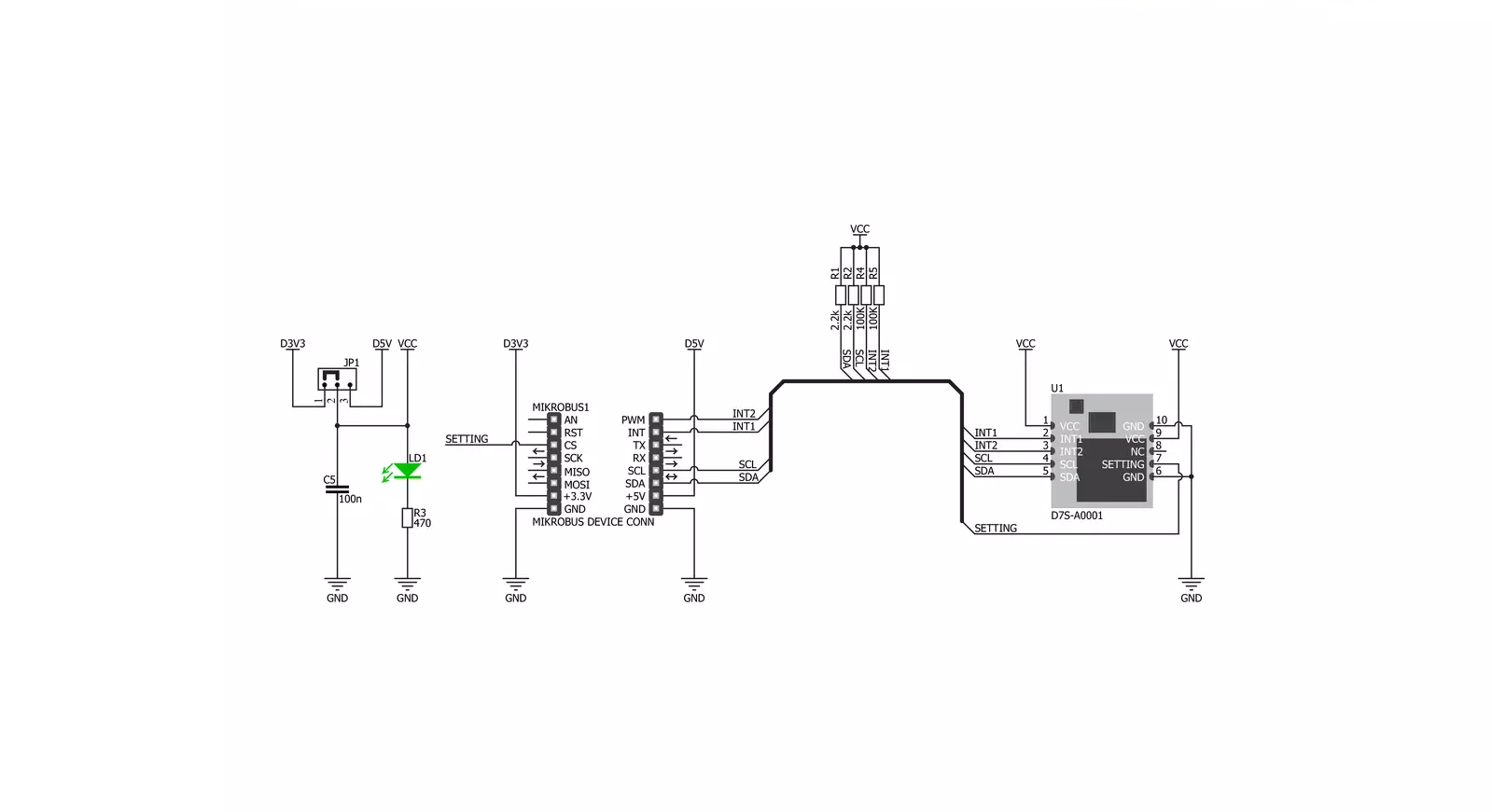
Take a closer look
Click board™ Schematic
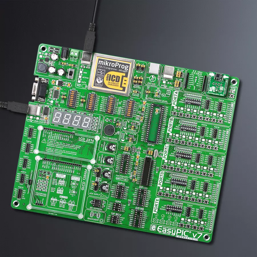
Step by step
Project assembly

Start by selecting your development board and Click board™. Begin with the EasyPIC v7 as your development board.


Software Support
Library Description
This library contains API for Earthquake Click driver.
Key functions:
earthquake_proc_notify- Shutoff output functionearthquake_read_status- Read status functionearthquake_read_si- Read SI function
Open Source
Code example
The complete application code and a ready-to-use project are available through the NECTO Studio Package Manager for direct installation in the NECTO Studio. The application code can also be found on the MIKROE GitHub account.
/*!
 * \file
 * \brief Earthquake Click example
 *
 * # Description
 * Intializes I2C module, LOG and GPIO structure, sets INT and PWM pins as
 * input and sets CS pin as output.
 *
 * The demo application is composed of two sections :
 *
 * ## Application Init
 * Intializes of I2C driver and makes initial log.
 *
 * ## Application Task
 * This is an example that shows most of the functions that Earthquake Click
 * has. Results are being sent to the Usart Terminal where you can track their
 * changes.
 *
 *
 * \author MikroE Team
 *
 */
// ------------------------------------------------------------------- INCLUDES

#include "board.h"
#include "log.h"
#include "earthquake.h"

// ------------------------------------------------------------------ VARIABLES

static earthquake_t earthquake;
static log_t logger;
uint16_t read_data;
uint8_t cnt;

void display_status( uint8_t status_data )
{
    if ( status_data == EARTHQUAKE_STANDBY_MODE )
    {
        log_printf( &logger, "Standby  Mode \r\n" );
    }

    if ( status_data == EARTHQUAKE_NORMAL_MODE )
    {
        log_printf( &logger, "Normal Mode \r\n" );
    }

    if ( status_data == EARTHQUAKE_INIT_INST )
    {
        log_printf( &logger, "Initial Installation Mode \r\n" );
    }

    if ( status_data == EARTHQUAKE_OFFSET_ACQ )
    {
        log_printf( &logger, "Offset Acquisition Mode \r\n" );
    }

    if ( status_data == EARTHQUAKE_SELF_DIAGNOSTIC )
    {
        log_printf( &logger, "Self-Diagnostic Mode \r\n" );
    }
}

void application_init ( void )
{
    log_cfg_t log_cfg;
    earthquake_cfg_t cfg;

    /**
     * Logger initialization.
     * Default baud rate: 115200
     * Default log level: LOG_LEVEL_DEBUG
     * @note If USB_UART_RX and USB_UART_TX
     * are defined as HAL_PIN_NC, you will
     * need to define them manually for log to work.
     * See @b LOG_MAP_USB_UART macro definition for detailed explanation.
     */
    LOG_MAP_USB_UART( log_cfg );
    log_init( &logger, &log_cfg );
    log_info( &logger, "---- Application Init ----" );

    //  Click initialization.
    earthquake_cfg_setup( &cfg );
    EARTHQUAKE_MAP_MIKROBUS( cfg, MIKROBUS_1 );
    earthquake_init( &earthquake, &cfg );
    Delay_ms ( 1000 );
    display_status( earthquake_read_status( &earthquake ) );
    Delay_ms ( 1000 );
    Delay_ms ( 1000 );
    earthquake_clear_memory( &earthquake );
    Delay_ms ( 1000 );
    Delay_ms ( 1000 );

    log_printf( &logger, "------------------------\r\n" );
    log_printf( &logger, "    Earthquake Click    \r\n" );
    log_printf( &logger, "------------------------\r\n" );
}

void application_task ( void )
{
    if ( earthquake_proc_notify( &earthquake ) )
    {
        log_printf( &logger, "  Earthquake detected!  \r\n" );
        log_printf( &logger, "------------------------\r\n" );
        Delay_ms ( 1000 );
        Delay_ms ( 1000 );

        for ( cnt = 20; cnt > 0; cnt-- )
        {
            log_printf( &logger, " Status : " );
            display_status( earthquake_read_status( &earthquake ) );

            read_data = earthquake_read_si( &earthquake );
            log_printf( &logger, " Max SI : %d\r\n", read_data );
            log_printf( &logger, "------------------------ \r\n" );
            Delay_ms ( 1000 );
            Delay_ms ( 1000 );
            Delay_ms ( 1000 );
            Delay_ms ( 1000 );
            Delay_ms ( 1000 );
        }

        earthquake_clear_memory( &earthquake );
        log_printf( &logger, " Afterquake  processing \r\n" );
        log_printf( &logger, "     please wait...     \r\n" );
        // 20 seconds delay
        Delay_ms ( 1000 );
        Delay_ms ( 1000 );
        Delay_ms ( 1000 );
        Delay_ms ( 1000 );
        Delay_ms ( 1000 );
        Delay_ms ( 1000 );
        Delay_ms ( 1000 );
        Delay_ms ( 1000 );
        Delay_ms ( 1000 );
        Delay_ms ( 1000 );
        Delay_ms ( 1000 );
        Delay_ms ( 1000 );
        Delay_ms ( 1000 );
        Delay_ms ( 1000 );
        Delay_ms ( 1000 );
        Delay_ms ( 1000 );
        Delay_ms ( 1000 );
        Delay_ms ( 1000 );
        Delay_ms ( 1000 );
        Delay_ms ( 1000 );

        log_printf( &logger, "------------------------\r\n" );
        log_printf( &logger, " Waiting for a quake... \r\n" );
        log_printf( &logger, "------------------------\r\n" );
    }
}

int main ( void )
{
    /* Do not remove this line or clock might not be set correctly. */
    #ifdef PREINIT_SUPPORTED
    preinit();
    #endif

    application_init( );

    for ( ; ; )
    {
        application_task( );
    }

    return 0;
}


// ------------------------------------------------------------------------ END


