Stay cool and informed with TSYS01 and PIC18LF26K80
Digital temperature mastery

Published Dec 29, 2023
Click board™
Thermo 9 Click
Dev. board
EasyPIC v7
Compiler
NECTO Studio
MCU
PIC18LF26K80
Harness the power of digital innovation with our temperature measurement solution, empowering you to master temperature control.
A
A
Hardware Overview
How does it work?
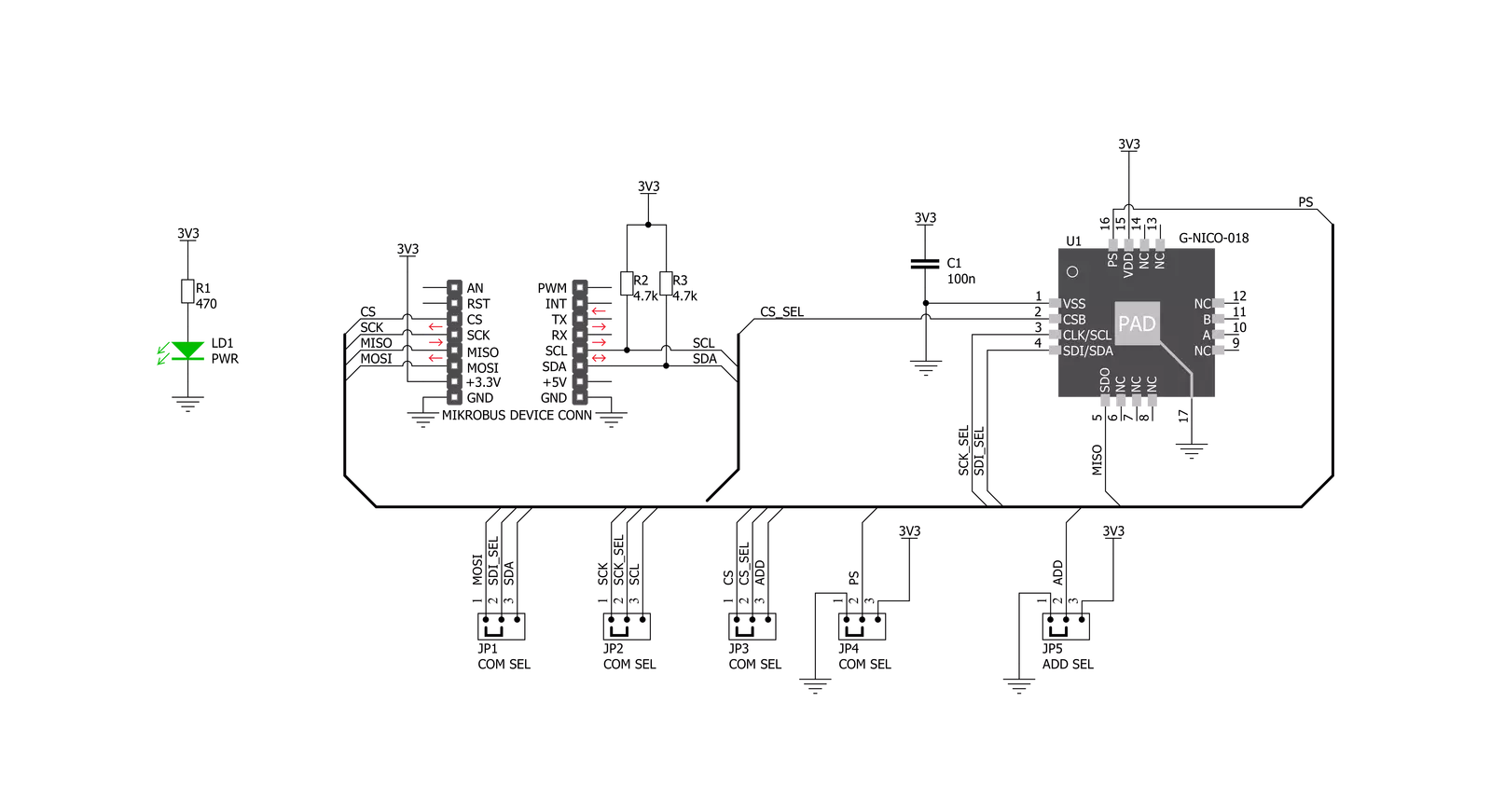
Thermo 9 Click is based on the TSYS01, a single device, versatile, new technology temperature sensor from TE Connectivity. The TSYS01 provides factory calibrated temperature information and it includes a temperature sensing chip and a 24-bit ΔΣ-ADC. The essence of the digital 24-bit temperature value and the internal calibration values lead to highly accurate temperature information accompanied by high measurement resolution. The TSYS01 can be interfaced to any microcontroller by an I2C or SPI interface. This microcontroller has to calculate the temperature result based on the ADC values and the calibration parameters. The TSYS01 has the SPI and the I2C Interface. When it comes to the I2C
communication, it starts with a start condition and it is ended by a stop condition. Each command consists of two bytes: the address byte and command byte. The SPI communication is a 4-wire SPI bus, operating as a slave. CS (chip select), SCLK (serial clock), SDI (serial data in), and SDO (serial data out) are used to interact with the SPI master. Communication with the chip starts when CS is pulled to low and ends when CS is pulled to high. SCLK is controlled by the SPI master and idles low (SCLK low on CS transitions, mode 0). A mode where the clock alternatively idles high is also supported (mode 3). The basic operating principles of the TSYS01 include several important features. Basically, converting
temperature into digital 16/24 bit ADC value and providing calibration coefficients while also providing ADC value and calibration coefficients by SPI or I2C interface. Given the most notable features of the Thermo 9 Click, it can be used for industrial control, replacement of thermistors and NTCs, heating/cooling systems, and HVAC. The design of the Click board™ itself is such that the thermal radiation from other components, which might affect the environmental temperature readings of the sensor, is reduced. The onboard SMD jumper labeled as VCC SEL allows voltage selection for interfacing with both 3.3V and 5V MCUs.

Features overview
Development board
EasyPIC v7 is the seventh generation of PIC development boards specially designed to develop embedded applications rapidly. It supports a wide range of 8-bit PIC microcontrollers from Microchip and has a broad set of unique functions, such as a powerful onboard mikroProg programmer and In-Circuit debugger over USB-B. The development board is well organized and designed so that the end-user has all the necessary elements in one place, such as switches, buttons, indicators, connectors, and others. With four different connectors for each port, EasyPIC v7 allows you to connect accessory boards, sensors, and custom electronics more efficiently than ever. Each part of
the EasyPIC v7 development board contains the components necessary for the most efficient operation of the same board. An integrated mikroProg, a fast USB 2.0 programmer with mikroICD hardware In-Circuit Debugger, offers many valuable programming/debugging options and seamless integration with the Mikroe software environment. Besides it also includes a clean and regulated power supply block for the development board. It can use various external power sources, including an external 12V power supply, 7-23V AC or 9-32V DC via DC connector/screw terminals, and a power source via the USB Type-B (USB-B) connector. Communication options such as
USB-UART and RS-232 are also included, alongside the well-established mikroBUS™ standard, three display options (7-segment, graphical, and character-based LCD), and several different DIP sockets. These sockets cover a wide range of 8-bit PIC MCUs, from PIC10F, PIC12F, PIC16F, PIC16Enh, PIC18F, PIC18FJ, and PIC18FK families. EasyPIC v7 is an integral part of the Mikroe ecosystem for rapid development. Natively supported by Mikroe software tools, it covers many aspects of prototyping and development thanks to a considerable number of different Click boards™ (over a thousand boards), the number of which is growing every day.

Microcontroller Overview
MCU Card / MCU
Architecture
PIC
MCU Memory (KB)
64
Silicon Vendor
Microchip
Pin count
28
RAM (Bytes)
3648
Used MCU Pins
mikroBUS™ mapper
Take a closer look
Click board™ Schematic
Step by step
Project assembly

Start by selecting your development board and Click board™. Begin with the EasyPIC v7 as your development board.


Software Support
Library Description
This library contains API for Thermo 9 Click driver.
Key functions:
thermo9_send_cmd- Function is used to send the command to the device.thermo9_calibation- Function resets and calibrates the device in order for it to work properly.thermo9_read_temp- Function is used to read temperature in degree centigrade.
Open Source
Code example
The complete application code and a ready-to-use project are available through the NECTO Studio Package Manager for direct installation in the NECTO Studio. The application code can also be found on the MIKROE GitHub account.
/*!
 * \file
 * \brief Thermo9 Click example
 *
 * # Description
 * This demoapp measures temperature every 3 seconds.
 *
 * The demo application is composed of two sections :
 *
 * ## Application Init
 * Logger initialization, Click initialization and calibration.
 *
 * ## Application Task
 * This example shows capabilities of Thermo 9 Click by measuring
 * temperature every 3 seconds and displaying temperature in degrres Celsius
 * via USART terminal.
 *
 * *note:*
 * Calibration function must be used once in order to get calibrations!
 *
 * \author Jovan Stajkovic
 *
 */
// ------------------------------------------------------------------- INCLUDES

#include "board.h"
#include "log.h"
#include "thermo9.h"

// ------------------------------------------------------------------ VARIABLES

static thermo9_t thermo9;
static log_t logger;
static float temp_val;

// ------------------------------------------------------ APPLICATION FUNCTIONS

void application_init ( void )
{
    log_cfg_t log_cfg;
    thermo9_cfg_t cfg;

    /**
     * Logger initialization.
     * Default baud rate: 115200
     * Default log level: LOG_LEVEL_DEBUG
     * @note If USB_UART_RX and USB_UART_TX
     * are defined as HAL_PIN_NC, you will
     * need to define them manually for log to work.
     * See @b LOG_MAP_USB_UART macro definition for detailed explanation.
     */
    LOG_MAP_USB_UART( log_cfg );
    log_init( &logger, &log_cfg );
    log_info( &logger, "---- Application Init ----" );

    //  Click initialization.

    thermo9_cfg_setup( &cfg );
    THERMO9_MAP_MIKROBUS( cfg, MIKROBUS_1 );
    thermo9_init( &thermo9, &cfg );
    Delay_ms ( 100 );
    log_printf( &logger, "---------------------\r\n" );
    log_printf( &logger, "    Thermo 9 Click   \r\n" );
    log_printf( &logger, "---------------------\r\n" );
    thermo9_calibation( &thermo9 );
    Delay_ms ( 100 );
    log_printf( &logger, "      Calibrated     \r\n" );
    log_printf( &logger, "---------------------\r\n" );
}

void application_task ( void )
{
    //  Task implementation.
    temp_val = thermo9_read_temp( &thermo9 );
    log_printf( &logger, "-- Temperature : %.2f C\r\n", temp_val );

    log_printf( &logger, "-----------------------------\r\n" );
    Delay_ms ( 1000 );
    Delay_ms ( 1000 );
}

int main ( void )
{
    /* Do not remove this line or clock might not be set correctly. */
    #ifdef PREINIT_SUPPORTED
    preinit();
    #endif

    application_init( );

    for ( ; ; )
    {
        application_task( );
    }

    return 0;
}


// ------------------------------------------------------------------------ END


