Detect the presence or lack of motion with ADXL345 and STM32F407VGT6
Measure acceleration in three different directions
Published Dec 29, 2023
Click board™
Accel Click
Dev. board
Clicker 4 for STM32F4
Compiler
NECTO Studio
MCU
STM32F407VGT6
Enhance your projects with accurate motion detection, capturing its speed and direction with precision
A
A
Hardware Overview
How does it work?
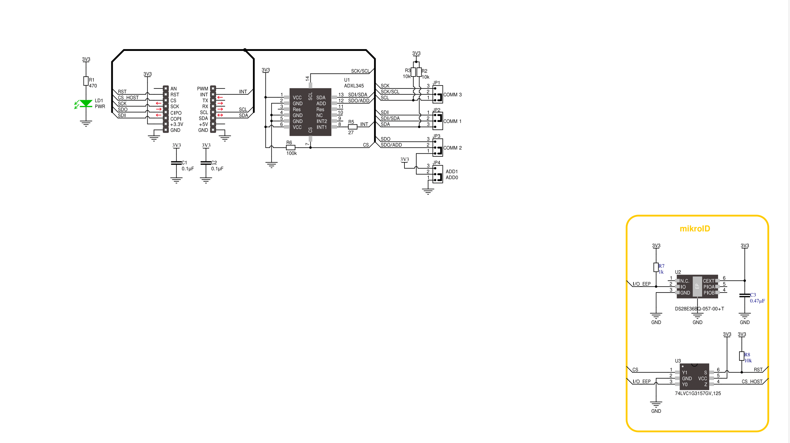
Accel Click is based on the ADXL345, a complete 3-axis acceleration measurement system that operates at low power consumption levels from Analog Devices. It measures both dynamic accelerations, resulting from motion or shock, and static acceleration, such as gravity, and allows selectable full-scale acceleration measurements in ranges of ±2g, ±4g, ±8g, or ±16g with a resolution of 4mg/LSB on the ±2g range. Acceleration is reported digitally, communicating via the SPI or the I2C protocol and providing 16-bit output resolution. Its high resolution also enables the measurement of inclination changes less than 1.0°. The ADXL345 supports several special sensing functions. Activity and inactivity sensing detect the presence or lack
of motion by comparing the acceleration on any axis with user-set thresholds, while tap sensing detects single and double taps in any direction. Besides, a free-fall sensing feature detects if the device is falling. All these functions can be mapped to the interrupt pin routed on the INT pin of the mikroBUS™ socket. Accel Click allows the use of both I2C and SPI interfaces. The selection can be made by positioning SMD jumpers labeled as COMM SEL in an appropriate position. Note that all the jumpers' positions must be on the same side, or the Click board™ may become unresponsive. While the I2C interface is selected, the ADXL345 allows choosing the least significant bit (LSB) of its I2C slave address using the SMD jumper labeled ADDR
SEL. An integrated memory management system with a 32-level first in, first out (FIFO) buffer can store data to minimize host processor activity and lower overall system power consumption. Low power modes enable intelligent motion-based power management with threshold sensing and active acceleration measurement at low power dissipation. This Click board™ can be operated only with a 3.3V logic voltage level. The board must perform appropriate logic voltage level conversion before using MCUs with different logic levels. Also, it comes equipped with a library containing functions and an example code that can be used as a reference for further development.

Features overview
Development board
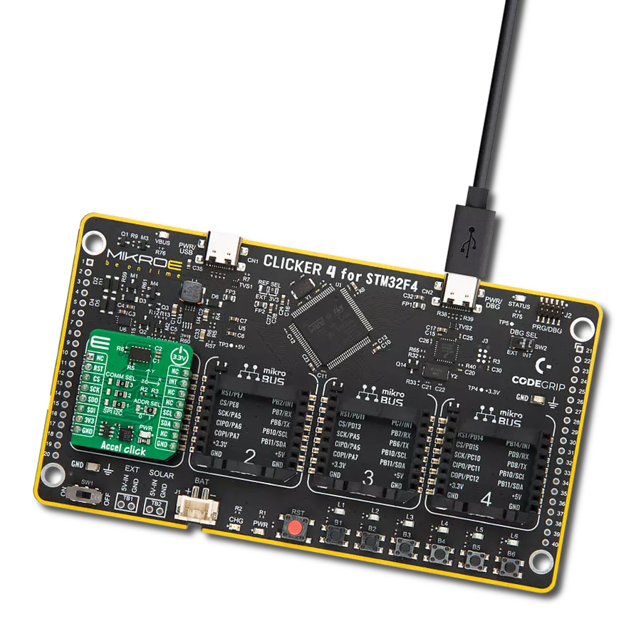
Clicker 4 for STM32F4 is a compact development board designed as a complete solution that you can use to quickly build your own gadgets with unique functionalities. Featuring an STM32F407VGT6 MCU, four mikroBUS™ sockets for Click boards™ connectivity, power management, and more, it represents a perfect solution for the rapid development of many different types of applications. At its core is an STM32F407VGT6 MCU, a powerful microcontroller by STMicroelectronics based on the high-performance
Arm® Cortex®-M4 32-bit processor core operating at up to 168 MHz frequency. It provides sufficient processing power for the most demanding tasks, allowing Clicker 4 to adapt to any specific application requirements. Besides two 1x20 pin headers, four improved mikroBUS™ sockets represent the most distinctive connectivity feature, allowing access to a huge base of Click boards™, growing on a daily basis. Each section of Clicker 4 is clearly marked, offering an intuitive and clean interface. This makes working with the
development board much simpler and, thus, faster. The usability of Clicker 4 doesn’t end with its ability to accelerate the prototyping and application development stages: it is designed as a complete solution that can be implemented directly into any project, with no additional hardware modifications required. Four mounting holes [4.2mm/0.165”] at all four corners allow simple installation by using mounting screws.

Microcontroller Overview
MCU Card / MCU

Architecture
ARM Cortex-M4
MCU Memory (KB)
10
Silicon Vendor
STMicroelectronics
Pin count
100
RAM (Bytes)
100
Used MCU Pins
mikroBUS™ mapper
Take a closer look
Click board™ Schematic
Step by step
Project assembly

Start by selecting your development board and Click board™. Begin with the Clicker 4 for STM32F4 as your development board.


Track your results in real time
Application Output
1. Application Output - In Debug mode, the 'Application Output' window enables real-time data monitoring, offering direct insight into execution results. Ensure proper data display by configuring the environment correctly using the provided tutorial.

2. UART Terminal - Use the UART Terminal to monitor data transmission via a USB to UART converter, allowing direct communication between the Click board™ and your development system. Configure the baud rate and other serial settings according to your project's requirements to ensure proper functionality. For step-by-step setup instructions, refer to the provided tutorial.

3. Plot Output - The Plot feature offers a powerful way to visualize real-time sensor data, enabling trend analysis, debugging, and comparison of multiple data points. To set it up correctly, follow the provided tutorial, which includes a step-by-step example of using the Plot feature to display Click board™ readings. To use the Plot feature in your code, use the function: plot(*insert_graph_name*, variable_name);. This is a general format, and it is up to the user to replace 'insert_graph_name' with the actual graph name and 'variable_name' with the parameter to be displayed.

Software Support
Library Description
This library contains API for Accel Click driver.
Key functions:
accel_read_x_axis- This function reads X axis value from Accelaccel_read_y_axis- This function reads Y axis value from Accelaccel_read_z_axis- This function reads Z axis value from Accel
Open Source
Code example
The complete application code and a ready-to-use project are available through the NECTO Studio Package Manager for direct installation in the NECTO Studio. The application code can also be found on the MIKROE GitHub account.
/*!
 * \file
 * \brief Accel Click example
 *
 * # Description
 * This example demonstrates the use of Accel Click board by reading and
 * displaying the accelerometer data (X, Y, and Z axis).
 *
 * The demo application is composed of two sections :
 *
 * ## Application Init
 * Initializes SPI/I2C driver and settings data read format,
 * power mode, FIFO control and baud rate ( 100Hz default ).
 *
 * ## Application Task
 * Reads X, Y and Z axis and logs on usbuart every 100 ms.
 *
 * \author Jovan Stajkovic
 *
 */
// ------------------------------------------------------------------- INCLUDES

#include "board.h"
#include "log.h"
#include "accel.h"

// ------------------------------------------------------------------ VARIABLES

static accel_t accel;
static log_t logger;

static uint8_t tmp;
static int16_t val_x;
static int16_t val_y;
static int16_t val_z;

// ------------------------------------------------------ APPLICATION FUNCTIONS

void application_init ( void )
{
    log_cfg_t log_cfg;
    accel_cfg_t cfg;

    /**
     * Logger initialization.
     * Default baud rate: 115200
     * Default log level: LOG_LEVEL_DEBUG
     * @note If USB_UART_RX and USB_UART_TX
     * are defined as HAL_PIN_NC, you will
     * need to define them manually for log to work.
     * See @b LOG_MAP_USB_UART macro definition for detailed explanation.
     */
    LOG_MAP_USB_UART( log_cfg );
    log_init( &logger, &log_cfg );
    log_info( &logger, " Application Init " );

    accel_cfg_setup( &cfg );
    ACCEL_MAP_MIKROBUS( cfg, MIKROBUS_1 );
    accel_init( &accel, &cfg );

    accel_generic_read( &accel, ACCEL_REG_DEVID, &tmp, 1 );

    if ( tmp == ACCEL_DEVID )
    {
        log_printf( &logger, "---- Comunication OK!!! ----\r\n" );
    }
    else
    {
        log_printf( &logger, "---- Comunication ERROR!!! ----\r\n" );
        for ( ; ; );
    }
    accel_default_cfg ( &accel );
}

void application_task ( void )
{
    val_x = accel_read_x_axis( &accel );
    log_printf( &logger, "Axis X : %.3f g\r\n", val_x / ACCEL_DATA_RES_LSB_PER_G );

    val_y = accel_read_y_axis( &accel );
    log_printf( &logger, "Axis Y : %.3f g\r\n", val_y / ACCEL_DATA_RES_LSB_PER_G );

    val_z = accel_read_z_axis( &accel );
    log_printf( &logger, "Axis Z : %.3f g\r\n", val_z / ACCEL_DATA_RES_LSB_PER_G );

    log_printf( &logger, "-------------------\r\n" );
    Delay_ms ( 100 );
}

int main ( void )
{
    /* Do not remove this line or clock might not be set correctly. */
    #ifdef PREINIT_SUPPORTED
    preinit();
    #endif

    application_init( );

    for ( ; ; )
    {
        application_task( );
    }

    return 0;
}


// ------------------------------------------------------------------------ END
Additional Support
Resources
Category:Motion


