Bridge the gap between I2C communication and the 1-Wire interface with DS28E17 and STM32F407VGT6
Simplify wiring and extend the reach of I2C devices across your projects

Published Mar 15, 2024
Click board™
1-Wire I2C click
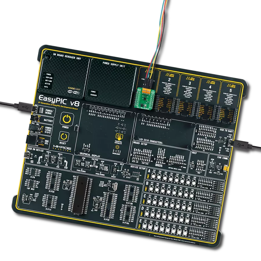
Dev. board
Clicker 4 for STM32F4
Compiler
NECTO Studio
MCU
STM32F407VGT6
Allow devices that traditionally communicate over I2C to be connected and interact over a 1-Wire interface
A
A
Hardware Overview
How does it work?
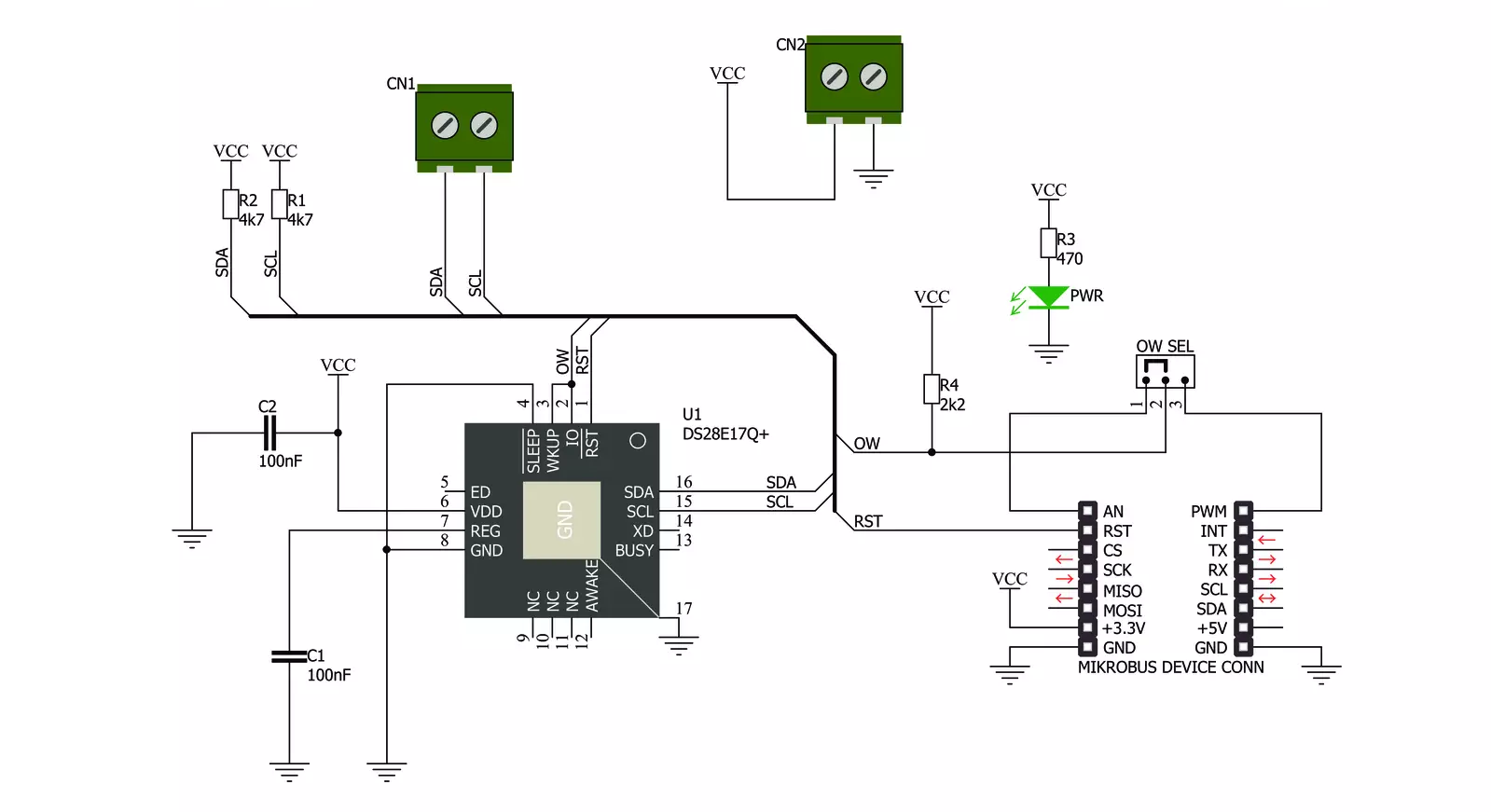
1-Wire I2C Click is based on the DS28E17, a 1-Wire-to-I2C master bridge from Analog Devices. The bridge supports 15Kbps and 77Kbps 1-Wire protocol with packetized I2C data payloads. The factory-programmed unique 64-bit 1-Wire ROM ID provides an unalterable serial number to the end equipment, thus allowing multiple DS8E17 devices to coexist with other devices in a 1-Wire network and be accessed individually without affecting other devices. The 1-Wire I2C Click allows
communication with complex I2C devices, such as displays, ADCs, DACs, sensors, and more. The bridge provides 1-Wire communication with only one I2C device. 1-Wire I2C Click uses the 1-Wire interface as a bridge to the standard 2-Wire I2C interface to communicate with the host MCU. You can choose a One-Wire input pin over the OW SEL jumper, where the OW1 is routed to an analog pin of the mikroBUS™ socket and is set by default. You can also reset the bridge over the RST pin. The I2C
device can be connected over a 4-pin screw terminal. This Click board™ can be operated only with a 3.3V logic voltage level. The board must perform appropriate logic voltage level conversion before using MCUs with different logic levels. Also, this Click board™ comes equipped with a library containing functions and an example code that can be used as a reference for further development.

Features overview
Development board
Clicker 4 for STM32F4 is a compact development board designed as a complete solution that you can use to quickly build your own gadgets with unique functionalities. Featuring an STM32F407VGT6 MCU, four mikroBUS™ sockets for Click boards™ connectivity, power management, and more, it represents a perfect solution for the rapid development of many different types of applications. At its core is an STM32F407VGT6 MCU, a powerful microcontroller by STMicroelectronics based on the high-performance
Arm® Cortex®-M4 32-bit processor core operating at up to 168 MHz frequency. It provides sufficient processing power for the most demanding tasks, allowing Clicker 4 to adapt to any specific application requirements. Besides two 1x20 pin headers, four improved mikroBUS™ sockets represent the most distinctive connectivity feature, allowing access to a huge base of Click boards™, growing on a daily basis. Each section of Clicker 4 is clearly marked, offering an intuitive and clean interface. This makes working with the
development board much simpler and, thus, faster. The usability of Clicker 4 doesn’t end with its ability to accelerate the prototyping and application development stages: it is designed as a complete solution that can be implemented directly into any project, with no additional hardware modifications required. Four mounting holes [4.2mm/0.165”] at all four corners allow simple installation by using mounting screws.

Microcontroller Overview
MCU Card / MCU

Architecture
ARM Cortex-M4
MCU Memory (KB)
10
Silicon Vendor
STMicroelectronics
Pin count
100
RAM (Bytes)
100
Used MCU Pins
mikroBUS™ mapper
Take a closer look
Click board™ Schematic
Step by step
Project assembly

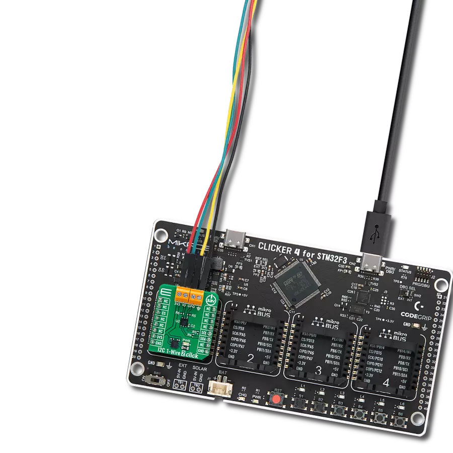
Start by selecting your development board and Click board™. Begin with the Clicker 4 for STM32F4 as your development board.


Software Support
Library Description
This library contains API for 1-Wire I2C Click driver.
Key functions:
c1wirei2c_reset_device- This function resets the device by toggling the RST pin statec1wirei2c_write_data- This function addresses and writes 1-255 bytes to an I2C slave without completing the transaction with a stopc1wirei2c_read_data_stop- This function is used to address and read 1-255 bytes from an I2C slave in one transaction
Open Source
Code example
The complete application code and a ready-to-use project are available through the NECTO Studio Package Manager for direct installation in the NECTO Studio. The application code can also be found on the MIKROE GitHub account.
/*!
* @file main.c
* @brief 1-Wire I2C Click Example.
*
* # Description
* This example demonstrates the use of 1-Wire I2C Click board by reading
* the temperature measurement from connected Thermo 4 Click board.
*
* The demo application is composed of two sections :
*
* ## Application Init
* Initializes the driver and performs the Click default configuration.
*
* ## Application Task
* Reads the temperature measurement from connected Thermo 4 Click board and
* displays the results on the USB UART once per second.
*
* @author Stefan Filipovic
*
*/
#include "board.h"
#include "log.h"
#include "c1wirei2c.h"
// Thermo 4 device settings
#define DEVICE_NAME "Thermo 4 Click"
#define DEVICE_SLAVE_ADDRESS 0x48
#define DEVICE_REG_TEMPERATURE 0x00
#define DEVICE_TEMPERATURE_RES 0.125f
static c1wirei2c_t c1wirei2c;
static log_t logger;
void application_init ( void )
{
log_cfg_t log_cfg; /**< Logger config object. */
c1wirei2c_cfg_t c1wirei2c_cfg; /**< Click config object. */
/**
* Logger initialization.
* Default baud rate: 115200
* Default log level: LOG_LEVEL_DEBUG
* @note If USB_UART_RX and USB_UART_TX
* are defined as HAL_PIN_NC, you will
* need to define them manually for log to work.
* See @b LOG_MAP_USB_UART macro definition for detailed explanation.
*/
LOG_MAP_USB_UART( log_cfg );
log_init( &logger, &log_cfg );
log_info( &logger, " Application Init " );
// Click initialization.
c1wirei2c_cfg_setup( &c1wirei2c_cfg );
C1WIREI2C_MAP_MIKROBUS( c1wirei2c_cfg, MIKROBUS_1 );
if ( ONE_WIRE_ERROR == c1wirei2c_init( &c1wirei2c, &c1wirei2c_cfg ) )
{
log_error( &logger, " Communication init." );
for ( ; ; );
}
if ( C1WIREI2C_ERROR == c1wirei2c_default_cfg ( &c1wirei2c ) )
{
log_error( &logger, " Default configuration." );
for ( ; ; );
}
log_info( &logger, " Application Task " );
}
void application_task ( void )
{
float temperature = 0;
uint8_t reg_data[ 2 ] = { 0 };
uint8_t reg_addr = DEVICE_REG_TEMPERATURE;
if ( ( C1WIREI2C_OK == c1wirei2c_write_data ( &c1wirei2c, DEVICE_SLAVE_ADDRESS, ®_addr, 1 ) ) &&
( C1WIREI2C_OK == c1wirei2c_read_data_stop ( &c1wirei2c, DEVICE_SLAVE_ADDRESS, reg_data, 2 ) ) )
{
temperature = ( ( ( int16_t ) ( ( ( uint16_t ) reg_data[ 0 ] << 8 ) |
reg_data[ 1 ] ) ) >> 5 ) * DEVICE_TEMPERATURE_RES;
log_printf( &logger, "\r\n%s - Temperature: %.3f degC\r\n", ( char * ) DEVICE_NAME, temperature );
}
else
{
log_error( &logger, "%s - no communication!\r\n", ( char * ) DEVICE_NAME );
}
Delay_ms ( 1000 );
}
int main ( void )
{
/* Do not remove this line or clock might not be set correctly. */
#ifdef PREINIT_SUPPORTED
preinit();
#endif
application_init( );
for ( ; ; )
{
application_task( );
}
return 0;
}
// ------------------------------------------------------------------------ END
Additional Support
Resources
Category:1-Wire