Simplify data transfer between USB and UART devices with CP2110 and STM32F407VGT6
From USB to UART in a blink!

Published Dec 29, 2023
Click board™
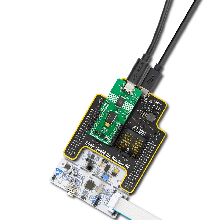
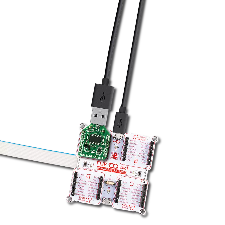
USB UART 5 Click
Dev. board
Clicker 4 for STM32F4
Compiler
NECTO Studio
MCU
STM32F407VGT6
Revolutionize your data communication projects with the USB to UART magic – a compact and efficient solution that connects your devices swiftly and flawlessly.
A
A
Hardware Overview
How does it work?
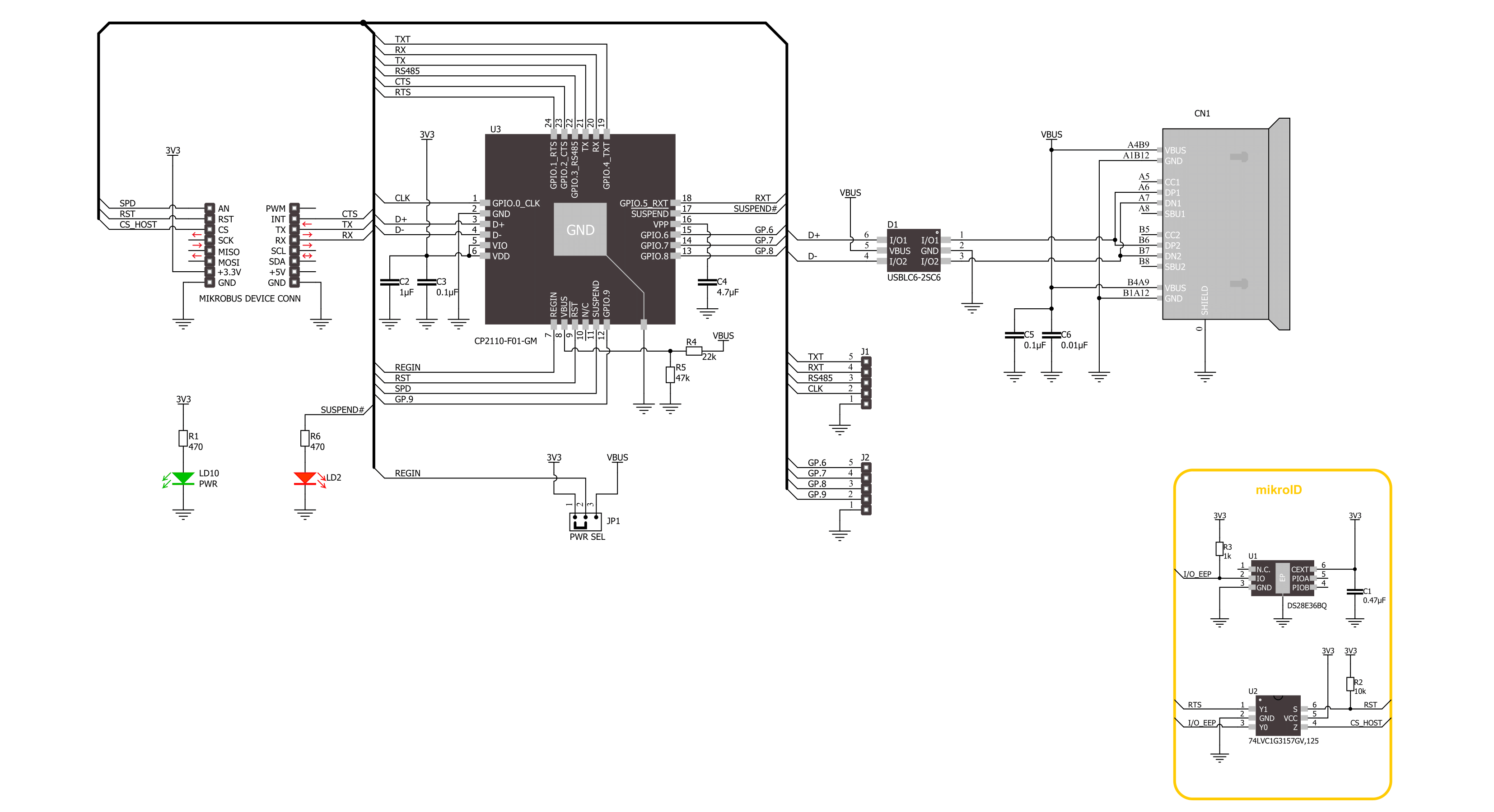
USB UART 5 Click is based on the CP2110, a single-chip HID USB to UART bridge controller from Silicon Labs. A USB function controller in the CP2110 is a USB 2.0-compliant, full-speed device with an integrated USB transceiver, one-time programmable ROM, and an asynchronous serial data bus (UART) in one compact package. The UART capabilities of the CP2110 include baud rate support from 300 to 1Mbps, hardware flow control, RS-485 support, and GPIO signals that are user-defined for status and control information. The USB function controller manages all data transfers between USB and UART, command requests generated by the USB host controller, and commands for controlling the function of the UARTs and GPIO pins. The CP2110 uses the standard USB HID device class, natively supported by most operating systems. A custom driver does
not need to be installed for this device. In addition, the CP2110 also supports USB Suspend and Resume modes for power management purposes. The CP2110 enters Suspend mode when Suspend signaling is detected on the bus using the SPD pin of the mikroBUS™ socket. Upon entering Suspend mode, the SPD signal is asserted, but it can also be asserted after a reset condition (RST pin) until device configuration during USB Enumeration is complete. SPD pin detects logic high level when the device is in the Suspend state and logic low when the device is in Normal mode, which is also visually indicated via red LED labeled as CONNECTED. This Click board™ also features 8 GPIO signals, located on unpopulated headers, that are user-defined for status and control information. Four GPIO signals support alternate features, including a configurable clock output
(CLK) from 24MHz to 47kHz, RS-485 transceiver control, and TX and RX LED toggle features. Also, the USB UART 5 Click can work in a USB-powered configuration thanks to the ability of the CP2110 to provide adequate power to all its parts with the help of an internal regulator using the USB bus voltage. To select this mode of operation, it is necessary to switch the jumper PWR SEL to the position marked with VBUS. This Click board™ can be operated only with a 3.3V logic voltage level. The board must perform appropriate logic voltage level conversion before using MCUs with different logic levels. Also, it comes equipped with a library containing functions and an example code that can be used as a reference for further development.

Features overview
Development board
Clicker 4 for STM32F4 is a compact development board designed as a complete solution that you can use to quickly build your own gadgets with unique functionalities. Featuring an STM32F407VGT6 MCU, four mikroBUS™ sockets for Click boards™ connectivity, power management, and more, it represents a perfect solution for the rapid development of many different types of applications. At its core is an STM32F407VGT6 MCU, a powerful microcontroller by STMicroelectronics based on the high-performance
Arm® Cortex®-M4 32-bit processor core operating at up to 168 MHz frequency. It provides sufficient processing power for the most demanding tasks, allowing Clicker 4 to adapt to any specific application requirements. Besides two 1x20 pin headers, four improved mikroBUS™ sockets represent the most distinctive connectivity feature, allowing access to a huge base of Click boards™, growing on a daily basis. Each section of Clicker 4 is clearly marked, offering an intuitive and clean interface. This makes working with the
development board much simpler and, thus, faster. The usability of Clicker 4 doesn’t end with its ability to accelerate the prototyping and application development stages: it is designed as a complete solution that can be implemented directly into any project, with no additional hardware modifications required. Four mounting holes [4.2mm/0.165”] at all four corners allow simple installation by using mounting screws.

Microcontroller Overview
MCU Card / MCU

Architecture
ARM Cortex-M4
MCU Memory (KB)
10
Silicon Vendor
STMicroelectronics
Pin count
100
RAM (Bytes)
100
Used MCU Pins
mikroBUS™ mapper
Take a closer look
Click board™ Schematic
Step by step
Project assembly

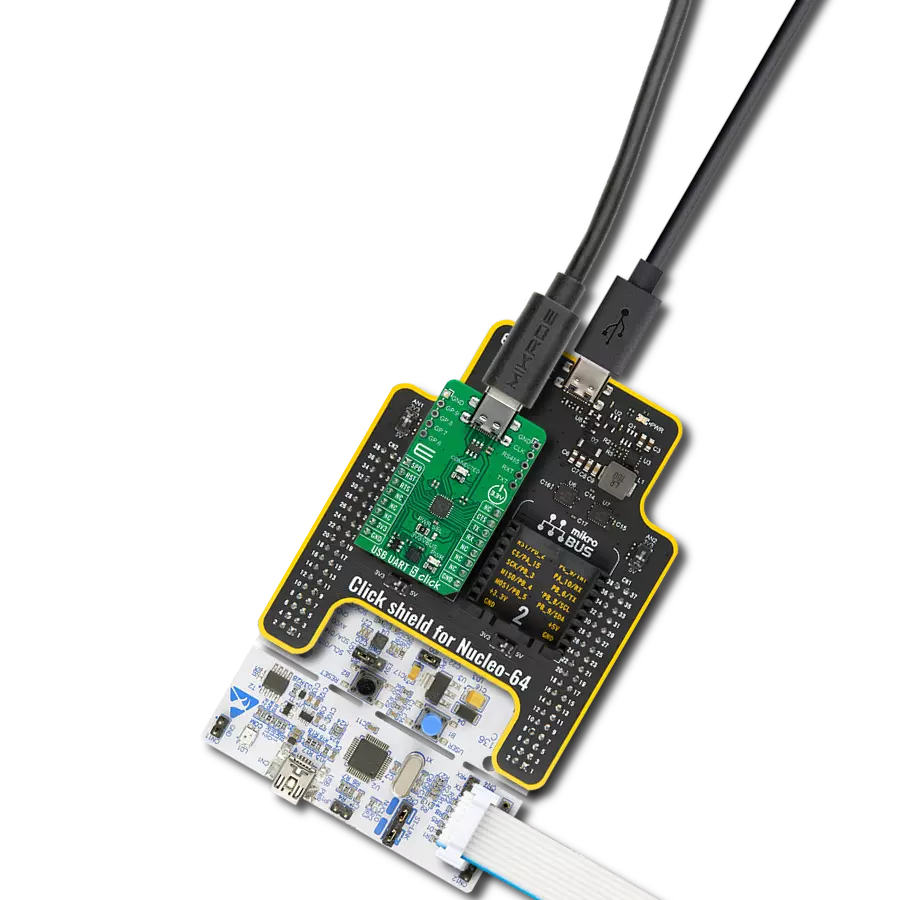
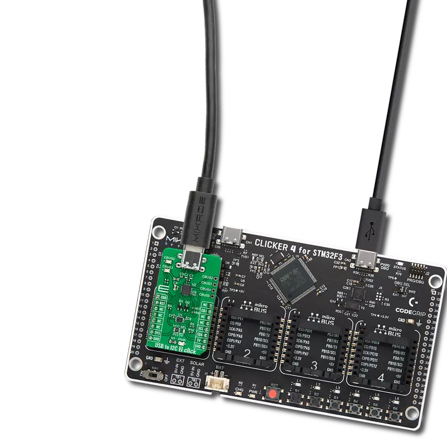
Start by selecting your development board and Click board™. Begin with the Clicker 4 for STM32F4 as your development board.


Software Support
Library Description
This library contains API for USB UART 5 Click driver.
Key functions:
usbuart5_generic_write- USB UART 5 data writing function.usbuart5_generic_read- USB UART 5 data reading function.usbuart5_reset_device- USB UART 5 reset the device function.
Open Source
Code example
The complete application code and a ready-to-use project are available through the NECTO Studio Package Manager for direct installation in the NECTO Studio. The application code can also be found on the MIKROE GitHub account.
/*!
 * @file main.c
 * @brief USB UART 5 Click Example.
 *
 * # Description
 * This example reads and processes data from USB UART 5 Click board™.
 * The library initializes and defines the UART bus drivers
 * to transmit or receive data.
 *
 * The demo application is composed of two sections :
 *
 * ## Application Init
 * Initializes driver, wake-up module, and performs the default configuration.
 *
 * ## Application Task
 * Any data which the host PC sends via HidUartExample
 * will be sent over USB to the Click board and then it will be read and
 * echoed back by the MCU to the PC where the terminal program will display it.
 * Results are being sent to the UART Terminal, where you can track their changes.
 *
 * @note
 * Make sure to download and install
 * CP2110/4 Software package for Windows/Mac/Linux on the host PC.
 *
 * @author Nenad Filipovic
 *
 */

#include "board.h"
#include "log.h"
#include "usbuart5.h"

static usbuart5_t usbuart5;
static log_t logger;

void application_init ( void )
{
    log_cfg_t log_cfg;  /**< Logger config object. */
    usbuart5_cfg_t usbuart5_cfg;  /**< Click config object. */

    /**
     * Logger initialization.
     * Default baud rate: 115200
     * Default log level: LOG_LEVEL_DEBUG
     * @note If USB_UART_RX and USB_UART_TX
     * are defined as HAL_PIN_NC, you will
     * need to define them manually for log to work.
     * See @b LOG_MAP_USB_UART macro definition for detailed explanation.
     */
    LOG_MAP_USB_UART( log_cfg );
    log_init( &logger, &log_cfg );
    log_info( &logger, " Application Init " );

    // Click initialization.
    usbuart5_cfg_setup( &usbuart5_cfg );
    USBUART5_MAP_MIKROBUS( usbuart5_cfg, MIKROBUS_1 );
    if ( UART_ERROR == usbuart5_init( &usbuart5, &usbuart5_cfg ) )
    {
        log_error( &logger, " Communication init." );
        for ( ; ; );
    }

    usbuart5_default_cfg ( &usbuart5 );
    log_info( &logger, " Application Task " );
}

void application_task ( void )
{
    char rx_data = 0;
    if ( usbuart5_generic_read ( &usbuart5, &rx_data, 1 ) )
    {
        if ( usbuart5_generic_write ( &usbuart5, &rx_data, 1 ) )
        {
            log_printf( &logger, "%c", rx_data );
        }
    }
}

int main ( void )
{
    /* Do not remove this line or clock might not be set correctly. */
    #ifdef PREINIT_SUPPORTED
    preinit();
    #endif

    application_init( );

    for ( ; ; )
    {
        application_task( );
    }

    return 0;
}

// ------------------------------------------------------------------------ END
Additional Support
Resources
Category:USB