Add ZigBee wireless communication into your projects with XB24CZ7PIS-004 and STM32F407VGT6
Provide wireless connectivity to end-point devices in ZigBee mesh networks

Published Mar 09, 2024
Click board™
XBEE Click
Development board
Clicker 4 for STM32F4
Compiler
NECTO Studio
MCU
STM32F407VGT6
High-performance XBee® RF module for extensive indoor and outdoor range, ensuring robust and globally accepted network solutions for energy and control systems
A
A
Hardware Overview
How does it work?
XBee Click is based on the XB24CZ7PIS-004, a low-power Digi XBee® RF module from Digi International, providing wireless connectivity to end-point devices in ZigBee mesh networks. The transceiver chipset of the XB24CZ7PIS-004 is based on the Ember Silicon Labs EM357 SoC with an RF data rate of 250kbps (serial up to 1Mbps) and advanced configuration options available via simple AT or API commands. It also supports low-power sleeping nodes and has an outdoor RF line-of-sight range of up to 1.2km (urban range of up to 60m) in a combination of coverage, data redundancy, and data reliability. The XB24CZ7PIS-004 module has worldwide acceptance. Operating at a frequency of 2.4GHz, it allows its application in the US, Canada, Europe, Australia, and Japan. The ZigBee module also supports various security levels that are configured depending on the application's needs. This Click board™ comes with a configurable host interface allowing communication with MCU using the chosen interface. The XB24CZ7PIS-004 can communicate
with MCU using the UART interface with commonly used UART RX, TX, and hardware flow control pins UART CTS and RTS (Clear to Send and Ready to Send) or using the SPI interface (XBee module will work as an SPI-slave only). The module can be configured locally through serial commands (AT or API) or remotely through remote API commands to set or read any network device's configuration settings. In the case of the SPI interface, the users can use it to configure the module and write the library by themselves. XBee Click is associated with many other features. An active-low reset signal routed on the RST pin of the mikroBUS™ socket activates a hardware reset of the system, while the A/D pin routed on the INT pin of the mikroBUS™ socket represents a type of interrupt whose function can be selected by positioning an onboard SMD jumper to an appropriate position labeled as DTR or ATT. DTR position is a "Data terminal ready" function used to tell the XBee module that the host MCU is ready to communicate, while the ATT position (SPI Attention) represents an indicator
for the SPI interface whenever the XBee module has data for the host MCU. Alongside firmware updates, it supports commissioning and LED behaviors; a commissioning pushbutton marked as COMMI combined with an ASSOC LED provides various simple functions to aid in deploying devices in a network, such as a device wake-up, broadcast transmission, and more. On the other side, the yellow ASSOC LED indicates the device's network status and diagnostics information. If the LED is constantly on, it means that the module is not connected to the network, while the standard flashing of the LED represents the normal operating mode. This Click board™ can be operated only with a 3.3V logic voltage level. The board must perform appropriate logic voltage level conversion before using MCUs with different logic levels. However, the Click board™ comes equipped with a library containing functions and an example code that can be used as a reference for further development.

Features overview
Development board
Clicker 4 for STM32F4 is a compact development board designed as a complete solution that you can use to quickly build your own gadgets with unique functionalities. Featuring an STM32F407VGT6 MCU, four mikroBUS™ sockets for Click boards™ connectivity, power management, and more, it represents a perfect solution for the rapid development of many different types of applications. At its core is an STM32F407VGT6 MCU, a powerful microcontroller by STMicroelectronics based on the high-performance
Arm® Cortex®-M4 32-bit processor core operating at up to 168 MHz frequency. It provides sufficient processing power for the most demanding tasks, allowing Clicker 4 to adapt to any specific application requirements. Besides two 1x20 pin headers, four improved mikroBUS™ sockets represent the most distinctive connectivity feature, allowing access to a huge base of Click boards™, growing on a daily basis. Each section of Clicker 4 is clearly marked, offering an intuitive and clean interface. This makes working with the
development board much simpler and, thus, faster. The usability of Clicker 4 doesn’t end with its ability to accelerate the prototyping and application development stages: it is designed as a complete solution that can be implemented directly into any project, with no additional hardware modifications required. Four mounting holes [4.2mm/0.165”] at all four corners allow simple installation by using mounting screws.

Microcontroller Overview
MCU Card / MCU

Architecture
ARM Cortex-M4
MCU Memory (KB)
10
Silicon Vendor
STMicroelectronics
Pin count
100
RAM (Bytes)
100
Used MCU Pins
mikroBUS™ mapper
Take a closer look
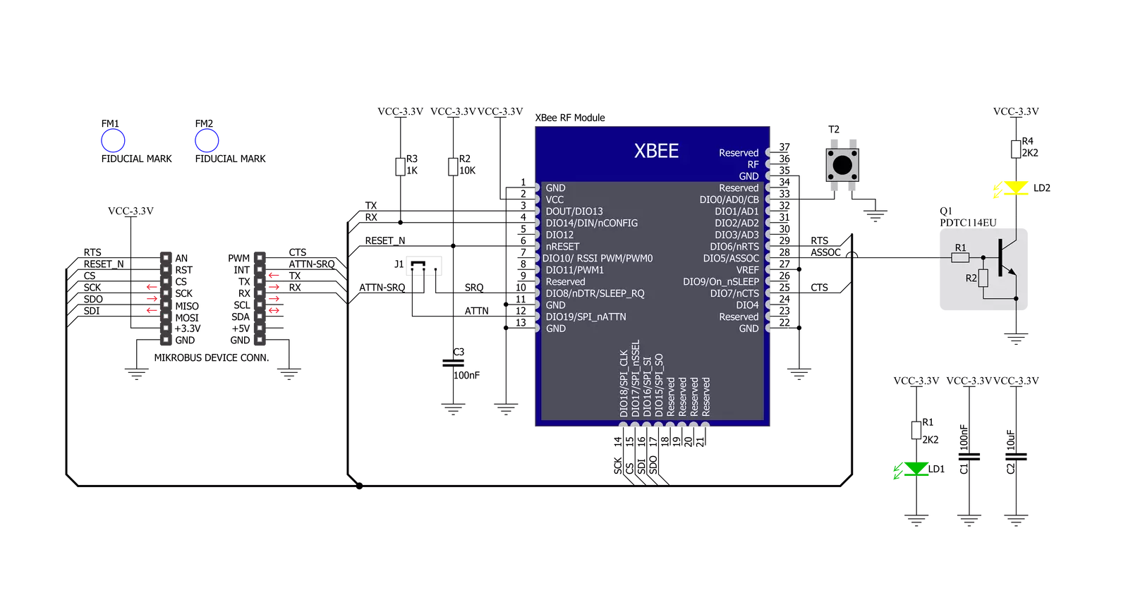
Schematic
Step by step
Project assembly

Start by selecting your development board and Click board™. Begin with the Clicker 4 for STM32F4 as your development board.


Track your results in real time
Application Output
After loading the code example, pressing the "DEBUG" button builds and programs it on the selected setup.

After programming is completed, a header with buttons for various actions available in the IDE appears. By clicking the green "PLAY "button, we start reading the results achieved with Click board™.

Upon completion of programming, the Application Output tab is automatically opened, where the achieved result can be read. In case of an inability to perform the Debug function, check if a proper connection between the MCU used by the setup and the CODEGRIP programmer has been established. A detailed explanation of the CODEGRIP-board connection can be found in the CODEGRIP User Manual. Please find it in the RESOURCES section.

Software Support
Library Description
This library contains API for XBEE Click driver.
Key functions:
xbee_get_serial_number- This function sends a get serial number commandxbee_set_device_name- This function sets the device name (node identifier)xbee_set_destination_address- This function sets the destination address high and low bytes
Open Source
Code example
This example can be found in NECTO Studio. Feel free to download the code, or you can copy the code below.
/*!
 * @file main.c
 * @brief XBEE Click Example.
 *
 * # Description
 * This example demonstrates the use of an XBEE click board by showing
 * the communication between the two click boards configured in transparent mode.
 *
 * The demo application is composed of two sections :
 *
 * ## Application Init
 * Initializes the driver and configures the click board by performing a factory reset,
 * and setting the device name, destination address, and api mode to transparent.
 *
 * ## Application Task
 * Depending on the selected application mode, it reads all the received data or
 * sends the desired message every 3 seconds.
 *
 * ## Additional Function
 * - static void xbee_clear_app_buf ( void )
 * - static err_t xbee_process ( void )
 * - static err_t xbee_display_rsp ( uint16_t timeout )
 *
 * @author Stefan Filipovic
 *
 */

#include "board.h"
#include "log.h"
#include "xbee.h"

// Device name (Node identifier).
#define DEVICE_NAME                 "XBEE Click"

// Enter here the specific serial number high and low bytes of the remote device as a hex string or
// leave it set to broadcast addresses for forwarding messages to all devices
#define DESTINATION_ADDRESS_HIGH    XBEE_BROADCAST_DEST_ADDRESS_HIGH
#define DESTINATION_ADDRESS_LOW     XBEE_BROADCAST_DEST_ADDRESS_LOW

// Comment out the line below in order to switch the application mode to receiver
#define DEMO_APP_TRANSMITTER

// Text message to send in the transmitter application mode
#define DEMO_TEXT_MESSAGE           "MIKROE - XBEE click board\r\n"

// Application process buffer size
#define PROCESS_BUFFER_SIZE         200

static xbee_t xbee;
static log_t logger;

static char app_buf[ PROCESS_BUFFER_SIZE ] = { 0 };
static int32_t app_buf_len = 0;

/**
 * @brief XBEE clearing application buffer.
 * @details This function clears memory of application buffer and reset its length and counter.
 * @note None.
 */
static void xbee_clear_app_buf ( void );

/**
 * @brief XBEE data reading function.
 * @details This function reads data from device and concatenates data to application buffer.
 * @return @li @c  0 - Read some data.
 *         @li @c -1 - Nothing is read.
 *         @li @c -2 - Application buffer overflow.
 * See #err_t definition for detailed explanation.
 * @note None.
 */
static err_t xbee_process ( void );

/**
 * @brief XBEE display response function.
 * @details This function reads data from device until it sends OK or ERROR message or until
 * it exceeds the timeout value.
 * @param[in] timeout : Timeout value in miliseconds.
 * @return @li @c  0 - Read some data.
 *         @li @c -1 - Nothing is read.
 * See #err_t definition for detailed explanation.
 * @note None.
 */
static err_t xbee_display_rsp ( uint16_t timeout );

void application_init ( void )
{
    log_cfg_t log_cfg;  /**< Logger config object. */
    xbee_cfg_t xbee_cfg;  /**< Click config object. */

    /**
     * Logger initialization.
     * Default baud rate: 115200
     * Default log level: LOG_LEVEL_DEBUG
     * @note If USB_UART_RX and USB_UART_TX
     * are defined as HAL_PIN_NC, you will
     * need to define them manually for log to work.
     * See @b LOG_MAP_USB_UART macro definition for detailed explanation.
     */
    LOG_MAP_USB_UART( log_cfg );
    log_init( &logger, &log_cfg );
    log_info( &logger, " Application Init " );

    // Click initialization.
    xbee_cfg_setup( &xbee_cfg );
    XBEE_MAP_MIKROBUS( xbee_cfg, MIKROBUS_1 );
    if ( UART_ERROR == xbee_init( &xbee, &xbee_cfg ) )
    {
        log_error( &logger, " Communication init." );
        for ( ; ; );
    }

    xbee_hw_reset ( &xbee );
    xbee_process( );
    xbee_clear_app_buf( );

    log_printf( &logger, " - Enter command mode -\r\n" );
    xbee_enter_command_mode ( &xbee );
    Delay_ms ( 100 );
    xbee_display_rsp ( 1000 );

    log_printf( &logger, " - Factory Reset -\r\n" );
    xbee_factory_reset ( &xbee );
    Delay_ms ( 100 );
    xbee_display_rsp ( 1000 );

    log_printf( &logger, " - Get serial number -\r\n" );
    xbee_get_serial_number ( &xbee );
    Delay_ms ( 100 );
    xbee_display_rsp ( 1000 );

    log_printf( &logger, " - Set Device Name -\r\n" );
    xbee_set_device_name ( &xbee, DEVICE_NAME );
    Delay_ms ( 100 );
    xbee_display_rsp ( 1000 );

    log_printf( &logger, " - Set Destination Address -\r\n" );
    xbee_set_destination_address ( &xbee, DESTINATION_ADDRESS_HIGH, DESTINATION_ADDRESS_LOW );
    Delay_ms ( 100 );
    xbee_display_rsp ( 1000 );

    log_printf( &logger, " - Set API mode -\r\n" );
    xbee_set_api_mode ( &xbee, XBEE_MODE_TRANSPARENT );
    Delay_ms ( 100 );
    xbee_display_rsp ( 1000 );

    log_printf( &logger, " - Apply changes -\r\n" );
    xbee_apply_changes ( &xbee );
    Delay_ms ( 100 );
    xbee_display_rsp ( 1000 );

    log_printf( &logger, " - Save changes -\r\n" );
    xbee_save_changes ( &xbee );
    Delay_ms ( 100 );
    xbee_display_rsp ( 1000 );

    log_printf( &logger, " - Exit command mode -\r\n" );
    xbee_exit_command_mode ( &xbee );
    Delay_ms ( 100 );
    xbee_display_rsp ( 1000 );

    app_buf_len = 0;

#ifdef DEMO_APP_TRANSMITTER
    log_printf( &logger, " Application Mode: Transmitter\r\n" );
#else
    log_printf( &logger, " Application Mode: Receiver\r\n" );
#endif

    log_info( &logger, " Application Task " );
}

void application_task ( void )
{
#ifdef DEMO_APP_TRANSMITTER
    xbee_generic_write( &xbee, DEMO_TEXT_MESSAGE, strlen( DEMO_TEXT_MESSAGE ) );
    log_printf( &logger, "%s", ( char * ) DEMO_TEXT_MESSAGE );
    Delay_ms( 3000 );
#else
    xbee_process( );
    if ( app_buf_len > 0 )
    {
        log_printf( &logger, "%s", app_buf );
        xbee_clear_app_buf(  );
    }
#endif
}

int main ( void )
{
    application_init( );

    for ( ; ; )
    {
        application_task( );
    }

    return 0;
}

static void xbee_clear_app_buf ( void )
{
    memset( app_buf, 0, app_buf_len );
    app_buf_len = 0;
}

static err_t xbee_process ( void )
{
    int32_t rx_size;
    char rx_buf[ PROCESS_BUFFER_SIZE ] = { 0 };
    rx_size = xbee_generic_read( &xbee, rx_buf, PROCESS_BUFFER_SIZE );
    if ( rx_size > 0 )
    {
        int32_t buf_cnt = 0;
        if ( ( app_buf_len + rx_size ) > PROCESS_BUFFER_SIZE )
        {
            xbee_clear_app_buf(  );
            return XBEE_ERROR;
        }
        else
        {
            buf_cnt = app_buf_len;
            app_buf_len += rx_size;
        }
        for ( int32_t rx_cnt = 0; rx_cnt < rx_size; rx_cnt++ )
        {
            if ( rx_buf[ rx_cnt ] != 0 )
            {
                app_buf[ ( buf_cnt + rx_cnt ) ] = rx_buf[ rx_cnt ];
            }
            else
            {
                app_buf_len--;
                buf_cnt--;
            }
        }
        return XBEE_OK;
    }
    return XBEE_ERROR;
}

static err_t xbee_display_rsp ( uint16_t timeout )
{
    uint16_t timeout_cnt = 0;
    xbee_process ( );
    while ( ( 0 == strstr( app_buf, XBEE_RSP_OK ) ) &&
            ( 0 == strstr( app_buf, XBEE_RSP_ERROR ) ) &&
            ( timeout_cnt++ < timeout ) )
    {
        xbee_process ( );
        Delay_ms ( 1 );
    }
    if ( app_buf_len > 0 )
    {
        for ( int32_t buf_cnt = 0; buf_cnt < app_buf_len; buf_cnt++ )
        {
            log_printf( &logger, "%c", app_buf[ buf_cnt ] );
        }
        xbee_clear_app_buf ( );
        log_printf( &logger, "--------------------------------\r\n" );
        return XBEE_OK;
    }
    return XBEE_ERROR;
}

// ------------------------------------------------------------------------ END


