Provide highly accurate and responsive illumination adjustments with TSL2584TSV and PIC18LF27K42
Light as data: Unleashing the potential of ambient light sensing
Published Jan 23, 2024
Click board™
Ambient 15 Click
Dev. board
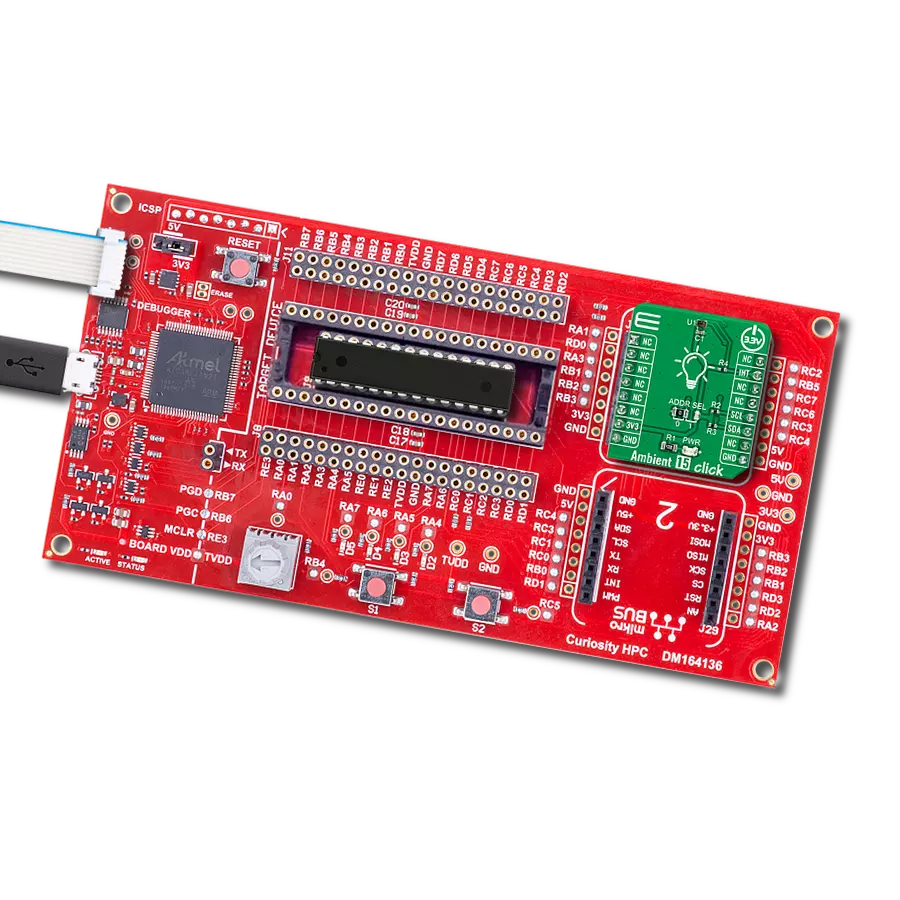
Curiosity HPC
Compiler
NECTO Studio
MCU
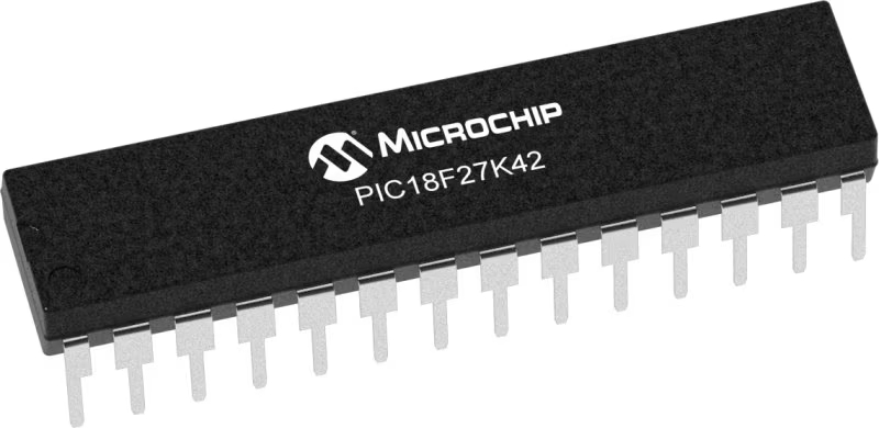
PIC18LF27K42
Our ambient light sensor is the invisible hand behind a more efficient, comfortable, and sustainable future – discover the difference today
A
A
Hardware Overview
How does it work?
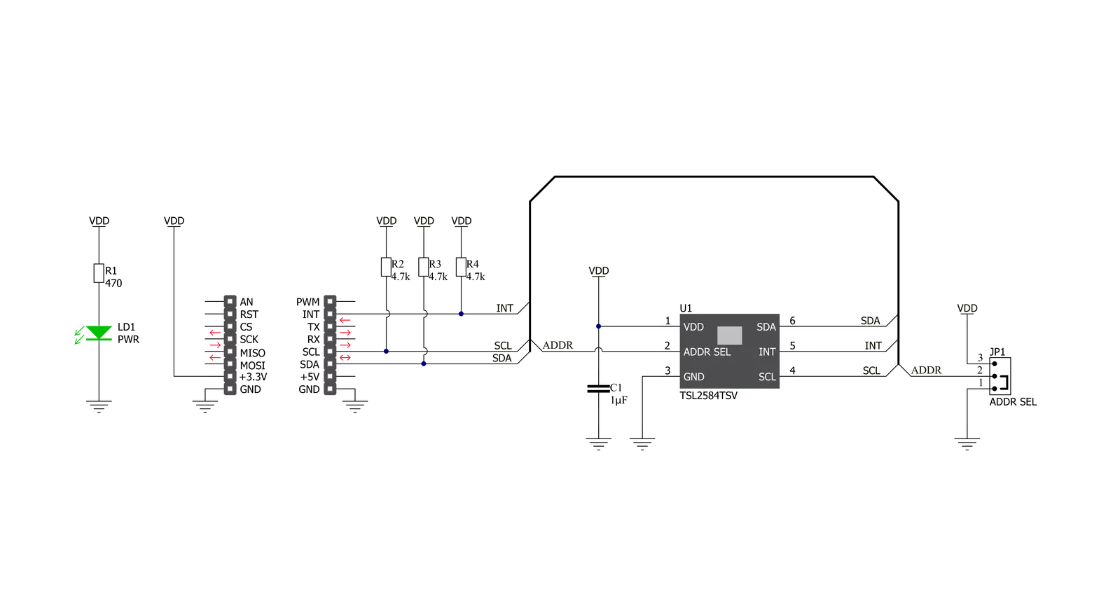
Ambient 15 Click is based on the TSL2584TSV, a high-sensitivity light-to-digital converter that transforms light intensity into a digital output signal from AMS-AG. Thanks to its near-photopic response, the TSL2584TSV can detect a wide range of highly accurate lux measurements up to 33klx, even when mounted behind dark glass. Filtering out unwanted IR light enables the sensor to accurately measure the ambient light accurately, thus producing a near-photopic response. It also has stable performance over a wide temperature range, suitable for measuring the present ambient light. The TSL2584TSV combines one broadband photodiode (visible plus infrared), one infrared-responding photodiode, and, as mentioned before, a photopic infrared-blocking filter
on a single CMOS integrated circuit. Two integrating analog-to-digital converters (ADC) convert the photodiode currents into a digital output representing the irradiance measured on each channel. Integration of both channels occurs simultaneously. Upon completion of the conversion cycle, the conversion result is transferred to the Channel 0 and Channel 1 data registers. The transfers are double-buffered to ensure that the integrity of the data is maintained. After the transfer, the device automatically begins the next integration cycle. Ambient 15 Click communicates with MCU using the standard I2C 2-Wire interface to read data and configure settings, supporting Standard Mode operation with a clock frequency of 100kHz and Fast
Mode up to 400kHz. Besides, the TSL2584TSV allows choosing the least significant bit (LSB) of its I2C slave address using the SMD jumper labeled ADDR SEL. It also possesses an additional interrupt signal, routed on the INT pin of the mikroBUS™ socket labeled as INT, indicating when a specific interrupt event occurs, such as detecting a meaningful change in light intensity. This Click board™ can be operated only with a 3.3V logic voltage level. The board must perform appropriate logic voltage level conversion before using MCUs with different logic levels. Also, it comes equipped with a library containing functions and an example code that can be used as a reference for further development.


Features overview
Development board
Curiosity HPC, standing for Curiosity High Pin Count (HPC) development board, supports 28- and 40-pin 8-bit PIC MCUs specially designed by Microchip for the needs of rapid development of embedded applications. This board has two unique PDIP sockets, surrounded by dual-row expansion headers, allowing connectivity to all pins on the populated PIC MCUs. It also contains a powerful onboard PICkit™ (PKOB), eliminating the need for an external programming/debugging tool, two mikroBUS™ sockets for Click board™ connectivity, a USB connector, a set of indicator LEDs, push button switches and a variable potentiometer. All
these features allow you to combine the strength of Microchip and Mikroe and create custom electronic solutions more efficiently than ever. Each part of the Curiosity HPC development board contains the components necessary for the most efficient operation of the same board. An integrated onboard PICkit™ (PKOB) allows low-voltage programming and in-circuit debugging for all supported devices. When used with the MPLAB® X Integrated Development Environment (IDE, version 3.0 or higher) or MPLAB® Xpress IDE, in-circuit debugging allows users to run, modify, and troubleshoot their custom software and hardware
quickly without the need for additional debugging tools. Besides, it includes a clean and regulated power supply block for the development board via the USB Micro-B connector, alongside all communication methods that mikroBUS™ itself supports. Curiosity HPC development board allows you to create a new application in just a few steps. Natively supported by Microchip software tools, it covers many aspects of prototyping thanks to many number of different Click boards™ (over a thousand boards), the number of which is growing daily.

Microcontroller Overview
MCU Card / MCU
Architecture
PIC
MCU Memory (KB)
128
Silicon Vendor
Microchip
Pin count
28
RAM (Bytes)
8192
Used MCU Pins
mikroBUS™ mapper
Take a closer look
Click board™ Schematic
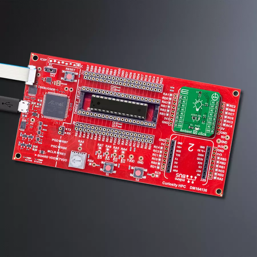
Step by step
Project assembly

Start by selecting your development board and Click board™. Begin with the Curiosity HPC as your development board.


Software Support
Library Description
This library contains API for Ambient 15 Click driver.
Key functions:
ambient15_set_atime- This function sets the timing register for the selected integration timeambient15_set_gain- This function sets the gain levelambient15_measure_light_level- This function reads the raw ADC data from two channels and then measures the light level in lux based on those readings
Open Source
Code example
The complete application code and a ready-to-use project are available through the NECTO Studio Package Manager for direct installation in the NECTO Studio. The application code can also be found on the MIKROE GitHub account.
/*!
 * @file main.c
 * @brief Ambient15 Click example
 *
 * # Description
 * This example demonstrates the use of Ambient 15 Click board by measuring
 * the ambient light level in Lux.
 *
 * The demo application is composed of two sections :
 *
 * ## Application Init
 * Initializes the driver and performs the Click default configuration.
 *
 * ## Application Task
 * Waits for the data ready interrupt, then reads the ambient light level in Lux
 * and displays the results on the USB UART. By default, the data ready interrupt triggers
 * upon every ADC cycle which will be performed every 200ms.
 *
 * @author Stefan Filipovic
 *
 */

#include "board.h"
#include "log.h"
#include "ambient15.h"

static ambient15_t ambient15;
static log_t logger;

void application_init ( void )
{
    log_cfg_t log_cfg;  /**< Logger config object. */
    ambient15_cfg_t ambient15_cfg;  /**< Click config object. */

    /**
     * Logger initialization.
     * Default baud rate: 115200
     * Default log level: LOG_LEVEL_DEBUG
     * @note If USB_UART_RX and USB_UART_TX
     * are defined as HAL_PIN_NC, you will
     * need to define them manually for log to work.
     * See @b LOG_MAP_USB_UART macro definition for detailed explanation.
     */
    LOG_MAP_USB_UART( log_cfg );
    log_init( &logger, &log_cfg );
    log_info( &logger, " Application Init " );

    // Click initialization.
    ambient15_cfg_setup( &ambient15_cfg );
    AMBIENT15_MAP_MIKROBUS( ambient15_cfg, MIKROBUS_1 );
    if ( I2C_MASTER_ERROR == ambient15_init( &ambient15, &ambient15_cfg ) )
    {
        log_error( &logger, " Communication init." );
        for ( ; ; );
    }

    if ( AMBIENT15_ERROR == ambient15_default_cfg ( &ambient15 ) )
    {
        log_error( &logger, " Default configuration." );
        for ( ; ; );
    }

    log_info( &logger, " Application Task " );
}

void application_task ( void )
{
    if ( !ambient15_get_int_pin ( &ambient15 ) )
    {
        uint16_t lux;
        if ( AMBIENT15_OK == ambient15_measure_light_level ( &ambient15, &lux ) )
        {
            log_printf ( &logger, " Ambient light level [Lux]: %u\r\n\n", lux );
        }
    }
}

int main ( void )
{
    /* Do not remove this line or clock might not be set correctly. */
    #ifdef PREINIT_SUPPORTED
    preinit();
    #endif

    application_init( );

    for ( ; ; )
    {
        application_task( );
    }

    return 0;
}

// ------------------------------------------------------------------------ END
Additional Support
Resources
Category:Optical


