Experience a new era of motion sensing with 820M1-0025 and PIC18F26K22
Revolutionize predictive maintenance by leveraging piezoelectric principles
Published Jan 23, 2024
Click board™
Piezo Accel Click
Dev. board
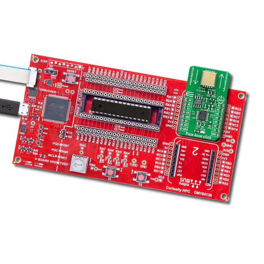
Curiosity HPC
Compiler
NECTO Studio
MCU
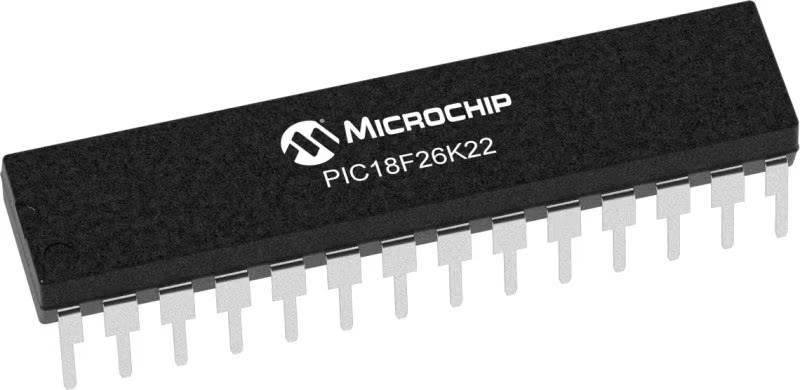
PIC18F26K22
Our cutting-edge piezoelectric accelerometer harnesses advanced technology to provide unparalleled vibration monitoring for early fault detection and proactive maintenance
A
A
Hardware Overview
How does it work?
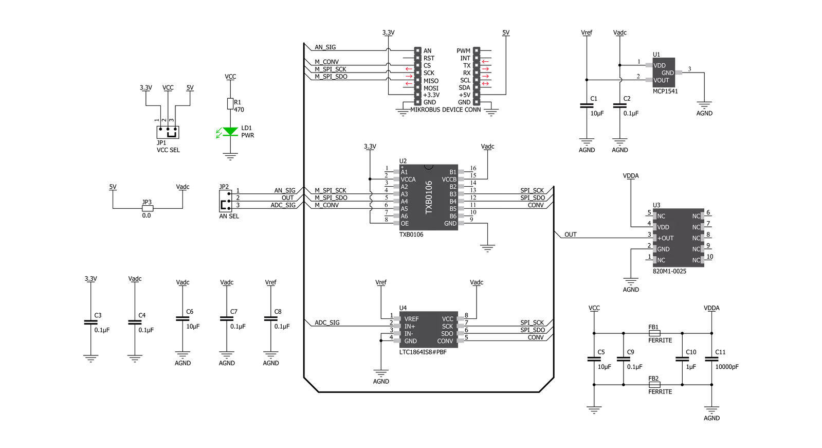
Piezo Accel Click is based on the 820M1-0025, a piezoelectric accelerometer designed for embedded condition monitoring and preventive maintenance applications from TE Connectivity. The 820M1-0025 accelerometer is available in the range of ±25g and features a flat frequency response up to >15kHz. Featuring stable piezoceramic crystals in shear mode sealed in a fully hermetic LCC package, the accelerometer incorporates an amplified ±1.25V output with optimum measurement resolution. This Click board™ is suitable for machine health monitoring and has superior resolution, dynamic range, and bandwidth to MEMS devices. The piezoelectric technology incorporated in the 820M1-0025 accelerometer has a proven track record for offering the reliable and long-term stable output
required for condition monitoring applications. This output signal can be processed in two ways: as an analog value or converted to a digital one using the LTC1864, a successive approximation A/D converter with a 16-bit resolution from Analog Devices. This ADC includes a sample-and-hold feature and has a differential analog input with an adjustable reference pin used as the reference input, resulting in accuracy and stability of the 4.096V reference voltage level provided by the MCP1541 from Microchip. Piezo Accel Click communicates with MCU using the 3-Wire SPI serial interface through an earlier-mentioned AD converter, the LTC1864. The 5V logic level provides a needed reference voltage for one side of the TXB0106, a 6-bit bidirectional level shifting, and a voltage translator with automatic direction
sensing from Texas Instruments. On the other side of the level shifter, the reference voltage is taken from the 3.3V pin from the mikroBUS™. In addition to the AD converter, the output of the 820M1-0025 can also be sent directly to an analog pin of the mikroBUS ™ socket labeled as AN. Output signal processing can be performed by placing an onboard SMD jumper labeled as AN SEL in an appropriate position marked as AN and ADC. This Click board™ can operate with either 3.3V or 5V logic voltage levels selected via the VCC SEL jumper. This way, both 3.3V and 5V capable MCUs can use the communication lines properly. Also, this Click board™ comes equipped with a library containing easy-to-use functions and an example code that can be used as a reference for further development.


Features overview
Development board
Curiosity HPC, standing for Curiosity High Pin Count (HPC) development board, supports 28- and 40-pin 8-bit PIC MCUs specially designed by Microchip for the needs of rapid development of embedded applications. This board has two unique PDIP sockets, surrounded by dual-row expansion headers, allowing connectivity to all pins on the populated PIC MCUs. It also contains a powerful onboard PICkit™ (PKOB), eliminating the need for an external programming/debugging tool, two mikroBUS™ sockets for Click board™ connectivity, a USB connector, a set of indicator LEDs, push button switches and a variable potentiometer. All
these features allow you to combine the strength of Microchip and Mikroe and create custom electronic solutions more efficiently than ever. Each part of the Curiosity HPC development board contains the components necessary for the most efficient operation of the same board. An integrated onboard PICkit™ (PKOB) allows low-voltage programming and in-circuit debugging for all supported devices. When used with the MPLAB® X Integrated Development Environment (IDE, version 3.0 or higher) or MPLAB® Xpress IDE, in-circuit debugging allows users to run, modify, and troubleshoot their custom software and hardware
quickly without the need for additional debugging tools. Besides, it includes a clean and regulated power supply block for the development board via the USB Micro-B connector, alongside all communication methods that mikroBUS™ itself supports. Curiosity HPC development board allows you to create a new application in just a few steps. Natively supported by Microchip software tools, it covers many aspects of prototyping thanks to many number of different Click boards™ (over a thousand boards), the number of which is growing daily.

Microcontroller Overview
MCU Card / MCU
Architecture
PIC
MCU Memory (KB)
64
Silicon Vendor
Microchip
Pin count
28
RAM (Bytes)
3896
Used MCU Pins
mikroBUS™ mapper
Take a closer look
Click board™ Schematic
Step by step
Project assembly

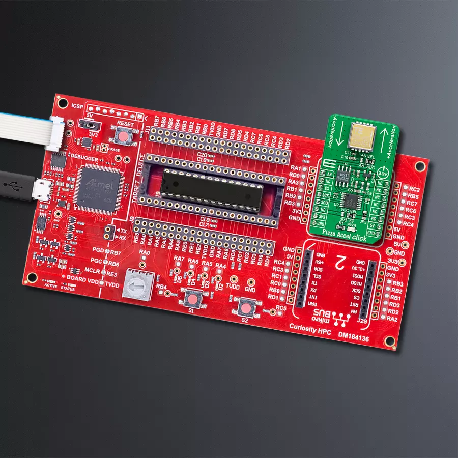
Start by selecting your development board and Click board™. Begin with the Curiosity HPC as your development board.


Track your results in real time
Application Output
1. Application Output - In Debug mode, the 'Application Output' window enables real-time data monitoring, offering direct insight into execution results. Ensure proper data display by configuring the environment correctly using the provided tutorial.

2. UART Terminal - Use the UART Terminal to monitor data transmission via a USB to UART converter, allowing direct communication between the Click board™ and your development system. Configure the baud rate and other serial settings according to your project's requirements to ensure proper functionality. For step-by-step setup instructions, refer to the provided tutorial.

3. Plot Output - The Plot feature offers a powerful way to visualize real-time sensor data, enabling trend analysis, debugging, and comparison of multiple data points. To set it up correctly, follow the provided tutorial, which includes a step-by-step example of using the Plot feature to display Click board™ readings. To use the Plot feature in your code, use the function: plot(*insert_graph_name*, variable_name);. This is a general format, and it is up to the user to replace 'insert_graph_name' with the actual graph name and 'variable_name' with the parameter to be displayed.

Software Support
Library Description
This library contains API for Piezo Accel Click driver.
Key functions:
piezoaccel_adc_raw_read- Piezo Accel read raw adc functionpiezoaccel_adc_voltage_read- Piezo Accel read adc converted to voltage functionpiezoaccel_g_unit_read- Piezo Accel read force of acceleration function
Open Source
Code example
The complete application code and a ready-to-use project are available through the NECTO Studio Package Manager for direct installation in the NECTO Studio. The application code can also be found on the MIKROE GitHub account.
/*!
 * @file main.c
 * @brief PiezoAccel Click example
 *
 * # Description
 * This application demonstrates the performance
 * of Piezo Accel Click board.
 *
 * The demo application is composed of two sections :
 *
 * ## Application Init
 * The initialization of UART LOG and SPI Click drivers.
 * Additionally, a default config is performed for
 * "out of the box" Piezo Accel Click settings.
 * Calibration is optional and is used to correct
 * the power supply offset of the sensor.
 *
 * ## Application Task
 * The ADC is constantly read and converted to a
 * g-force acceleration unit. Data is sent via LOG
 * every 20 ms and works on MikroPlot for graphical
 * representation of the sensor results.
 *
 * *note:*
 * This demo app is intended to be used with MikroPlot data
 * visualization tool for clear understanding of the results.
 * https://www.mikroe.com/mikroplot-data-visualization-tool
 *
 * @author Stefan Nikolic
 *
 */

#include "board.h"
#include "log.h"
#include "piezoaccel.h"

static piezoaccel_t piezoaccel;
static log_t logger;

static piezoaccel_setup_t setup_cfg_data;
static double time_var = 0;
static const int time_incr = 20;


void application_init ( void ) {
    log_cfg_t log_cfg;                  /**< Logger config object. */
    piezoaccel_cfg_t piezoaccel_cfg;    /**< Click config object. */

    /**
     * Logger initialization.
     * Default baud rate: 115200
     * Default log level: LOG_LEVEL_DEBUG
     * @note If USB_UART_RX and USB_UART_TX
     * are defined as HAL_PIN_NC, you will
     * need to define them manually for log to work.
     * See @b LOG_MAP_USB_UART macro definition for detailed explanation.
     */
    LOG_MAP_USB_UART( log_cfg );
    log_init( &logger, &log_cfg );
    log_info( &logger, " Application Init " );

    // Click initialization.

    piezoaccel_cfg_setup( &piezoaccel_cfg );
    PIEZOACCEL_MAP_MIKROBUS( piezoaccel_cfg, MIKROBUS_1 );
    err_t init_flag = piezoaccel_init( &piezoaccel, &piezoaccel_cfg );
    if ( init_flag == SPI_MASTER_ERROR ) {
        log_error( &logger, " Application Init Error. " );
        log_info( &logger, " Please, run program again... " );

        for ( ; ; );
    }

    piezoaccel_default_cfg( &piezoaccel, &setup_cfg_data );
    log_info( &logger, " Application Task " );
    Delay_ms ( 200 );
}

void application_task ( void ) {
    float read_val;

    read_val = piezoaccel_g_unit_read( &piezoaccel, &setup_cfg_data );
    log_printf( &logger, "%.2f,%.2f\r\n", read_val, time_var );
    time_var += time_incr;
    Delay_ms ( time_incr );
}

int main ( void )
{
    /* Do not remove this line or clock might not be set correctly. */
    #ifdef PREINIT_SUPPORTED
    preinit();
    #endif

    application_init( );

    for ( ; ; )
    {
        application_task( );
    }

    return 0;
}

// ------------------------------------------------------------------------ END
Additional Support
Resources
Category:Motion


