Provide highly accurate and responsive illumination adjustments with TSL2584TSV and PIC18F57Q43
Light as data: Unleashing the potential of ambient light sensing

Published Feb 13, 2024
Click board™
Ambient 15 Click
Dev. board
Curiosity Nano with PIC18F57Q43
Compiler
NECTO Studio
MCU
PIC18F57Q43
Our ambient light sensor is the invisible hand behind a more efficient, comfortable, and sustainable future – discover the difference today
A
A
Hardware Overview
How does it work?
Ambient 15 Click is based on the TSL2584TSV, a high-sensitivity light-to-digital converter that transforms light intensity into a digital output signal from AMS-AG. Thanks to its near-photopic response, the TSL2584TSV can detect a wide range of highly accurate lux measurements up to 33klx, even when mounted behind dark glass. Filtering out unwanted IR light enables the sensor to accurately measure the ambient light accurately, thus producing a near-photopic response. It also has stable performance over a wide temperature range, suitable for measuring the present ambient light. The TSL2584TSV combines one broadband photodiode (visible plus infrared), one infrared-responding photodiode, and, as mentioned before, a photopic infrared-blocking filter
on a single CMOS integrated circuit. Two integrating analog-to-digital converters (ADC) convert the photodiode currents into a digital output representing the irradiance measured on each channel. Integration of both channels occurs simultaneously. Upon completion of the conversion cycle, the conversion result is transferred to the Channel 0 and Channel 1 data registers. The transfers are double-buffered to ensure that the integrity of the data is maintained. After the transfer, the device automatically begins the next integration cycle. Ambient 15 Click communicates with MCU using the standard I2C 2-Wire interface to read data and configure settings, supporting Standard Mode operation with a clock frequency of 100kHz and Fast
Mode up to 400kHz. Besides, the TSL2584TSV allows choosing the least significant bit (LSB) of its I2C slave address using the SMD jumper labeled ADDR SEL. It also possesses an additional interrupt signal, routed on the INT pin of the mikroBUS™ socket labeled as INT, indicating when a specific interrupt event occurs, such as detecting a meaningful change in light intensity. This Click board™ can be operated only with a 3.3V logic voltage level. The board must perform appropriate logic voltage level conversion before using MCUs with different logic levels. Also, it comes equipped with a library containing functions and an example code that can be used as a reference for further development.


Features overview
Development board
PIC18F57Q43 Curiosity Nano evaluation kit is a cutting-edge hardware platform designed to evaluate microcontrollers within the PIC18-Q43 family. Central to its design is the inclusion of the powerful PIC18F57Q43 microcontroller (MCU), offering advanced functionalities and robust performance. Key features of this evaluation kit include a yellow user LED and a responsive
mechanical user switch, providing seamless interaction and testing. The provision for a 32.768kHz crystal footprint ensures precision timing capabilities. With an onboard debugger boasting a green power and status LED, programming and debugging become intuitive and efficient. Further enhancing its utility is the Virtual serial port (CDC) and a debug GPIO channel (DGI
GPIO), offering extensive connectivity options. Powered via USB, this kit boasts an adjustable target voltage feature facilitated by the MIC5353 LDO regulator, ensuring stable operation with an output voltage ranging from 1.8V to 5.1V, with a maximum output current of 500mA, subject to ambient temperature and voltage constraints.

Microcontroller Overview
MCU Card / MCU

Architecture
PIC
MCU Memory (KB)
128
Silicon Vendor
Microchip
Pin count
48
RAM (Bytes)
8196
You complete me!
Accessories
Curiosity Nano Base for Click boards is a versatile hardware extension platform created to streamline the integration between Curiosity Nano kits and extension boards, tailored explicitly for the mikroBUS™-standardized Click boards and Xplained Pro extension boards. This innovative base board (shield) offers seamless connectivity and expansion possibilities, simplifying experimentation and development. Key features include USB power compatibility from the Curiosity Nano kit, alongside an alternative external power input option for enhanced flexibility. The onboard Li-Ion/LiPo charger and management circuit ensure smooth operation for battery-powered applications, simplifying usage and management. Moreover, the base incorporates a fixed 3.3V PSU dedicated to target and mikroBUS™ power rails, alongside a fixed 5.0V boost converter catering to 5V power rails of mikroBUS™ sockets, providing stable power delivery for various connected devices.

Used MCU Pins
mikroBUS™ mapper
Take a closer look
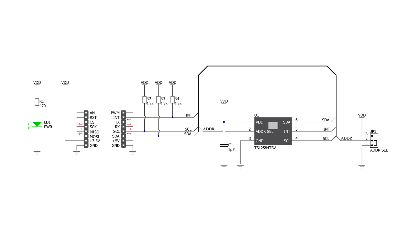
Click board™ Schematic
Step by step
Project assembly

Start by selecting your development board and Click board™. Begin with the Curiosity Nano with PIC18F57Q43 as your development board.


Track your results in real time
Application Output
1. Application Output - In Debug mode, the 'Application Output' window enables real-time data monitoring, offering direct insight into execution results. Ensure proper data display by configuring the environment correctly using the provided tutorial.

2. UART Terminal - Use the UART Terminal to monitor data transmission via a USB to UART converter, allowing direct communication between the Click board™ and your development system. Configure the baud rate and other serial settings according to your project's requirements to ensure proper functionality. For step-by-step setup instructions, refer to the provided tutorial.

3. Plot Output - The Plot feature offers a powerful way to visualize real-time sensor data, enabling trend analysis, debugging, and comparison of multiple data points. To set it up correctly, follow the provided tutorial, which includes a step-by-step example of using the Plot feature to display Click board™ readings. To use the Plot feature in your code, use the function: plot(*insert_graph_name*, variable_name);. This is a general format, and it is up to the user to replace 'insert_graph_name' with the actual graph name and 'variable_name' with the parameter to be displayed.

Software Support
Library Description
This library contains API for Ambient 15 Click driver.
Key functions:
ambient15_set_atime- This function sets the timing register for the selected integration timeambient15_set_gain- This function sets the gain levelambient15_measure_light_level- This function reads the raw ADC data from two channels and then measures the light level in lux based on those readings
Open Source
Code example
The complete application code and a ready-to-use project are available through the NECTO Studio Package Manager for direct installation in the NECTO Studio. The application code can also be found on the MIKROE GitHub account.
/*!
 * @file main.c
 * @brief Ambient15 Click example
 *
 * # Description
 * This example demonstrates the use of Ambient 15 Click board by measuring
 * the ambient light level in Lux.
 *
 * The demo application is composed of two sections :
 *
 * ## Application Init
 * Initializes the driver and performs the Click default configuration.
 *
 * ## Application Task
 * Waits for the data ready interrupt, then reads the ambient light level in Lux
 * and displays the results on the USB UART. By default, the data ready interrupt triggers
 * upon every ADC cycle which will be performed every 200ms.
 *
 * @author Stefan Filipovic
 *
 */

#include "board.h"
#include "log.h"
#include "ambient15.h"

static ambient15_t ambient15;
static log_t logger;

void application_init ( void )
{
    log_cfg_t log_cfg;  /**< Logger config object. */
    ambient15_cfg_t ambient15_cfg;  /**< Click config object. */

    /**
     * Logger initialization.
     * Default baud rate: 115200
     * Default log level: LOG_LEVEL_DEBUG
     * @note If USB_UART_RX and USB_UART_TX
     * are defined as HAL_PIN_NC, you will
     * need to define them manually for log to work.
     * See @b LOG_MAP_USB_UART macro definition for detailed explanation.
     */
    LOG_MAP_USB_UART( log_cfg );
    log_init( &logger, &log_cfg );
    log_info( &logger, " Application Init " );

    // Click initialization.
    ambient15_cfg_setup( &ambient15_cfg );
    AMBIENT15_MAP_MIKROBUS( ambient15_cfg, MIKROBUS_1 );
    if ( I2C_MASTER_ERROR == ambient15_init( &ambient15, &ambient15_cfg ) )
    {
        log_error( &logger, " Communication init." );
        for ( ; ; );
    }

    if ( AMBIENT15_ERROR == ambient15_default_cfg ( &ambient15 ) )
    {
        log_error( &logger, " Default configuration." );
        for ( ; ; );
    }

    log_info( &logger, " Application Task " );
}

void application_task ( void )
{
    if ( !ambient15_get_int_pin ( &ambient15 ) )
    {
        uint16_t lux;
        if ( AMBIENT15_OK == ambient15_measure_light_level ( &ambient15, &lux ) )
        {
            log_printf ( &logger, " Ambient light level [Lux]: %u\r\n\n", lux );
        }
    }
}

int main ( void )
{
    /* Do not remove this line or clock might not be set correctly. */
    #ifdef PREINIT_SUPPORTED
    preinit();
    #endif

    application_init( );

    for ( ; ; )
    {
        application_task( );
    }

    return 0;
}

// ------------------------------------------------------------------------ END
Additional Support
Resources
Category:Optical


