Develop a highly effective power management solution with MAX77654 and STM32F031K6
Elevate your batteries with our expertise

Published Oct 01, 2024
Click board™
BATT-MAN 2 Click
Dev. board
Nucleo 32 with STM32F031K6 MCU
Compiler
NECTO Studio
MCU
STM32F031K6
Ensure precise charging, safeguard against overcharging and overheating, and monitor battery health in real time
A
A
Hardware Overview
How does it work?
BATT-MAN 2 Click is based on the MAX77654, a highly-integrated battery charging and power management solution for low-power applications from Analog Devices. It features a single-inductor, multiple-output (SIMO) buck-boost regulator efficiently that provides three independently programmable power rails available on onboard terminals labeled VSB0, VSB1, and VSB2. Also, it has one 100mA LDO output, labeled as VLDO, with ripple rejection for audio and other noise-sensitive applications. This LDO output can also be configured as a load switch to manage power consumption by disconnecting external blocks when not required. The LDO output can be activated/deactivated by populating the JP2 onboard jumper. The MAX77654 also has an integrated highly-configurable linear charger that supports a wide range of Li+ battery capacities with a wide range of charge current and charger termination voltage options, featuring battery temperature monitoring for additional safety (JEITA). The charger feature is OFF when the CHG
supply is invalid (supply range from 4.1V up to 7.25V), disabled, or with a fresh battery. In addition to all the output terminals on this board, another one is marked with VSYS, the system power output terminal. In addition to providing power to the system resources and the device's control logic, VSYS is also designed for external use. BATT-MAN 2 Click communicates with MCU using the standard I2C 2-Wire interface for configuring and checking the device's status. Since the sensor for operation requires a 1.8V logic voltage level to work correctly, a small regulating LDO is used, the ADP160 from Analog Devices, providing a 1.8V out of mikroBUS™ rails. That's why the voltage-level translator is also featured. The I2C interface bus lines are routed to the dual bidirectional voltage-level translator, allowing this Click board™ to work properly with 3.3V and 5V MCUs. An onboard switch labeled as ENABLE primarily generates a wake-up signal for the PMIC that turns ON the regulators by setting the switch to an appropriate position marked as 1 or 0. In addition, this Click
board™ also has some additional features, such as a Reset routed to the RST pin on the mikroBUS™ socket used to hold the processor in a Reset state when the device is powered down. It also uses an interrupt pin, the INT pin of the mikroBUS™ socket, to signal an essential change in device status, while the three additional LED indicators, red, yellow, and blue LEDs labeled as LED2, LED3, and LED4, can be used for optional user-configurable visual indication. Besides, this device includes an analog multiplexer (AMX), routed to the AN pin on the mikroBUS™ socket, that switches several internal voltage and current signals to an external node for monitoring with an external ADC. This Click board™ can operate with either 3.3V or 5V logic voltage levels selected via the VCC SEL jumper. This way, both 3.3V and 5V capable MCUs can use the communication lines properly. Also, this Click board™ comes equipped with a library containing easy-to-use functions and an example code that can be used, as a reference, for further development.

Features overview
Development board
Nucleo 32 with STM32F031K6 MCU board provides an affordable and flexible platform for experimenting with STM32 microcontrollers in 32-pin packages. Featuring Arduino™ Nano connectivity, it allows easy expansion with specialized shields, while being mbed-enabled for seamless integration with online resources. The
board includes an on-board ST-LINK/V2-1 debugger/programmer, supporting USB reenumeration with three interfaces: Virtual Com port, mass storage, and debug port. It offers a flexible power supply through either USB VBUS or an external source. Additionally, it includes three LEDs (LD1 for USB communication, LD2 for power,
and LD3 as a user LED) and a reset push button. The STM32 Nucleo-32 board is supported by various Integrated Development Environments (IDEs) such as IAR™, Keil®, and GCC-based IDEs like AC6 SW4STM32, making it a versatile tool for developers.

Microcontroller Overview
MCU Card / MCU

Architecture
ARM Cortex-M0
MCU Memory (KB)
32
Silicon Vendor
STMicroelectronics
Pin count
32
RAM (Bytes)
4096
You complete me!
Accessories
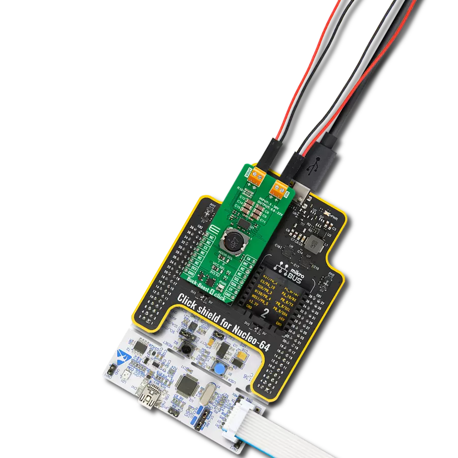
Click Shield for Nucleo-32 is the perfect way to expand your development board's functionalities with STM32 Nucleo-32 pinout. The Click Shield for Nucleo-32 provides two mikroBUS™ sockets to add any functionality from our ever-growing range of Click boards™. We are fully stocked with everything, from sensors and WiFi transceivers to motor control and audio amplifiers. The Click Shield for Nucleo-32 is compatible with the STM32 Nucleo-32 board, providing an affordable and flexible way for users to try out new ideas and quickly create prototypes with any STM32 microcontrollers, choosing from the various combinations of performance, power consumption, and features. The STM32 Nucleo-32 boards do not require any separate probe as they integrate the ST-LINK/V2-1 debugger/programmer and come with the STM32 comprehensive software HAL library and various packaged software examples. This development platform provides users with an effortless and common way to combine the STM32 Nucleo-32 footprint compatible board with their favorite Click boards™ in their upcoming projects.

Used MCU Pins
mikroBUS™ mapper
Take a closer look
Click board™ Schematic

Step by step
Project assembly

Start by selecting your development board and Click board™. Begin with the Nucleo 32 with STM32F031K6 MCU as your development board.


Software Support
Library Description
This library contains API for BATT-MAN 2 Click driver.
Key functions:
battman2_set_charger_enable- BATT-MAN 2 set charger enable functionbattman2_set_charger_cfg- BATT-MAN 2 set charger configuration functionbattman2_get_charger_cfg- BATT-MAN 2 get charger configuration function
Open Source
Code example
The complete application code and a ready-to-use project are available through the NECTO Studio Package Manager for direct installation in the NECTO Studio. The application code can also be found on the MIKROE GitHub account.
/*!
 * @file main.c
 * @brief BATTMAN2 Click example
 *
 * # Description
 * This library contains API for BATT-MAN 2 Click driver.
 * The library initializes and defines the I2C bus drivers
 * to write and read data from registers.
 * The library also includes a function for configuring appropriate charge current,
 * charge voltage, prequalification voltage,
 * Buck, Buck-Boost and Linear regulator configuration, etc.
 *
 * The demo application is composed of two sections :
 *
 * ## Application Init
 * The initialization of the I2C module, log UART, and additional pins.
 * After the driver inits and executes a default configuration,
 * the app disables charging, sets charger configuration,
 * enables charging, displays charger configuration,
 * or sets Buck-Boost configuration.
 *
 * ## Application Task
 * This is an example that shows the use of a BATT-MAN 2 Click board™.
 * The choice of example profile tasks depends on uncommented code.
 * Examples profile: CHARGER and BUCK-BOOST.
 * In the CHARGER profile, while on the BATT-MAN 2 Click board™ the
 * blue LED is the battery charging indicator,
 * while the red LED indicates the cessation of battery charging.
 * The yellow LED is an indicator of the BUCK-BOOST profile.
 * Results are being sent to the USART terminal where the user can track their changes.
 *
 * ## Additional Function
 * - static void display_charger_status ( void )
 * - static void display_sbb_status ( void )
 *
 * @author Nenad Filipovic
 *
 */

#include "board.h"
#include "log.h"
#include "battman2.h"

#define CHARGER
// #define BUCKBOOST

static battman2_t battman2;
static log_t logger;
static battman2_chg_cnfg_t chg_cfg;
static battman2_stat_chg_t chg_stat;
static battman2_sbb_cnfg_t sbb_cfg;
static uint8_t sbb_sel;

static void display_charger_status ( void )
{
    log_printf( &logger, " Charger Details :\r\n" );
    if ( chg_stat.chg_dtls == BATTMAN2_CHG_DTLS_OFF )
    {
        log_printf( &logger, "\tOff.\r\n" );
    }
    if ( chg_stat.chg_dtls == BATTMAN2_CHG_DTLS_PREQUALIFICATION_MODE )
    {
        log_printf( &logger, "\tPrequalification mode.\r\n" );
    }
    if ( chg_stat.chg_dtls == BATTMAN2_CHG_DTLS_FAST_CHARGE_CONSTANT_CURRENT )
    {
        log_printf( &logger, "\tFast-charge constant-current (CC) mode.\r\n" );
    }
    if ( chg_stat.chg_dtls == BATTMAN2_CHG_DTLS_JEITA_MODIFIED_FAST_CHRG_CC )
    {
        log_printf( &logger, "\tJEITA modified fast-charge constantcurrent mode.\r\n" );
    }
    if ( chg_stat.chg_dtls == BATTMAN2_CHG_DTLS_FAST_CHARGE_CONSTANT_VOLTAGE )
    {
        log_printf( &logger, "\tFast-charge constant-voltage (CV) mode.\r\n" );
    }
    if ( chg_stat.chg_dtls == BATTMAN2_CHG_DTLS_JEITA_MODIFIED_FAST_CHRG_CV )
    {
        log_printf( &logger, "\tJEITA modified fast-charge constant voltage (CV) mode.\r\n" );
    }
    if ( chg_stat.chg_dtls == BATTMAN2_CHG_DTLS_TOP_OFF_MODE )
    {
        log_printf( &logger, "\tTop-off mode.\r\n" );
    }
    if ( chg_stat.chg_dtls == BATTMAN2_CHG_DTLS_JEITA_MODIFIED_TOP_OFF_MODE )
    {
        log_printf( &logger, "\tJEITA modified top-off mode.\r\n" );
    }
    if ( chg_stat.chg_dtls == BATTMAN2_CHG_DTLS_DONE )
    {
        log_printf( &logger, "\tDone.\r\n" );
    }
    if ( chg_stat.chg_dtls == BATTMAN2_CHG_DTLS_JEITA_MODIFIED_DONE )
    {
        log_printf( &logger, "\tJEITA modified done.\r\n" );
    }
    if ( chg_stat.chg_dtls == BATTMAN2_CHG_DTLS_PREQUALIFICATION_TIMER_FAULT )
    {
        log_printf( &logger, "\tPrequalification timer fault.\r\n" );
    }
    if ( chg_stat.chg_dtls == BATTMAN2_CHG_DTLS_FAST_CHARGE_TIMER_FAULT )
    {
        log_printf( &logger, "\tFast-charge timer fault.\r\n" );
    }
    if ( chg_stat.chg_dtls == BATTMAN2_CHG_DTLS_BATTERY_TEMPERATURE_FAULT )
    {
        log_printf( &logger, "\tBattery temperature fault.\r\n" );
    }

    log_printf( &logger, " Quick Charger Status :\r\n" );
    if ( chg_stat.chg == BATTMAN2_CHG_NO_CHARGING )
    {
        log_printf( &logger, "\tCharging is not happening.\r\n" );
        battman2_set_gpio_output( &battman2, BATTMAN2_SEL_LED_RED, BATTMAN2_PIN_STATE_ON );
        battman2_set_gpio_output( &battman2, BATTMAN2_SEL_LED_YELLOW, BATTMAN2_PIN_STATE_OFF );
        battman2_set_gpio_output( &battman2, BATTMAN2_SEL_LED_BLUE, BATTMAN2_PIN_STATE_OFF );
    }
     if ( chg_stat.chg == BATTMAN2_CHG_CHARGING )
    {
        log_printf( &logger, "\tCharging is happening.\r\n" );
        battman2_set_gpio_output( &battman2, BATTMAN2_SEL_LED_RED, BATTMAN2_PIN_STATE_OFF );
        battman2_set_gpio_output( &battman2, BATTMAN2_SEL_LED_YELLOW, BATTMAN2_PIN_STATE_OFF );
        battman2_set_gpio_output( &battman2, BATTMAN2_SEL_LED_BLUE, BATTMAN2_PIN_STATE_ON );
    }
    log_printf( &logger, "-----------------------------------------------\r\n" );
}

static void display_sbb_status ( void )
{
    log_printf( &logger, "\tSBB Channel    : VSB-%d\r\n", ( uint16_t ) sbb_sel );
    log_printf( &logger, "\tOperation Mode :" );
    if ( sbb_cfg.op_mode == BATTMAN2_OP_MODE_BUCK_AND_BOOST )
    {
        log_printf( &logger, " Buck-boost mode.\r\n" );
    }
    if ( sbb_cfg.op_mode == BATTMAN2_OP_MODE_BUCK )
    {
        log_printf( &logger, " Buck mode.\r\n" );
    }

    log_printf( &logger, "\tCurrent Limit  :" );
    if ( sbb_cfg.current_limit == BATTMAN2_CURRENT_LIMIT_1000_mA )
    {
        log_printf( &logger, " 1.000 A\r\n" );
    }
    if ( sbb_cfg.current_limit == BATTMAN2_CURRENT_LIMIT_750_mA )
    {
        log_printf( &logger, " 0.750 A\r\n" );
    }
    if ( sbb_cfg.current_limit == BATTMAN2_CURRENT_LIMIT_500_mA )
    {
        log_printf( &logger, " 0.500 A\r\n" );
    }
    if ( sbb_cfg.current_limit == BATTMAN2_CURRENT_LIMIT_333_mA )
    {
        log_printf( &logger, " 0.333 A\r\n" );
    }

    log_printf( &logger, "\tOutput Voltage : %.3f V\r\n", sbb_cfg.output_vtg );
    log_printf( &logger, "-----------------------------------------------\r\n" );
}

void application_init ( void )
{
    log_cfg_t log_cfg;            /**< Logger config object. */
    battman2_cfg_t battman2_cfg;  /**< Click config object. */

    /**
     * Logger initialization.
     * Default baud rate: 115200
     * Default log level: LOG_LEVEL_DEBUG
     * @note If USB_UART_RX and USB_UART_TX
     * are defined as HAL_PIN_NC, you will
     * need to define them manually for log to work.
     * See @b LOG_MAP_USB_UART macro definition for detailed explanation.
     */
    LOG_MAP_USB_UART( log_cfg );
    log_init( &logger, &log_cfg );
    log_info( &logger, " Application Init " );

    // Click initialization.
    battman2_cfg_setup( &battman2_cfg );
    BATTMAN2_MAP_MIKROBUS( battman2_cfg, MIKROBUS_1 );
    err_t init_flag = battman2_init( &battman2, &battman2_cfg );
    if ( I2C_MASTER_ERROR == init_flag )
    {
        log_error( &logger, " Application Init Error. " );
        log_info( &logger, " Please, run program again... " );

        for ( ; ; );
    }

    battman2_default_cfg ( &battman2 );
    log_info( &logger, " Application Task " );
    Delay_ms ( 100 );

    battman2_set_charger_enable( &battman2, BATTMAN2_SET_CHARGER_DISABLE );
    Delay_ms ( 100 );

    #ifdef CHARGER
        log_printf( &logger, "-----------------------------------------------\r\n" );
        log_printf( &logger, "                Example: CHARGER               \r\n" );

        chg_cfg.thm_hot           = BATTMAN2_THM_HOT_411_mV;
        chg_cfg.thm_warm          = BATTMAN2_THM_WARM_511_mV;
        chg_cfg.thm_cool          = BATTMAN2_THM_COOL_747_mV;
        chg_cfg.thm_cold          = BATTMAN2_THM_COLD_867_mV;
        chg_cfg.vchgin_min        = 4.2;
        chg_cfg.ichgin_lim        = 95.0;
        chg_cfg.i_pq              = BATTMAN2_I_PQ_10_PERCENTAGE;
        chg_cfg.chg_pq            = 3.0;
        chg_cfg.i_term            = BATTMAN2_I_TERM_5_PERCENTAGE;
        chg_cfg.t_topoff          = BATTMAN2_T_TOPOFF_0_MIN;
        chg_cfg.tj_reg            = BATTMAN2_TJ_REG_60_C;
        chg_cfg.vsys_reg          = 4.100;
        chg_cfg.chg_cc            = 112.5;
        chg_cfg.t_fast_chg        = BATTMAN2_T_FAST_CHG_TIMER_7_HOURS;
        chg_cfg.chg_cc_jeita      = 15.0;
        chg_cfg.thm_en            = BATTMAN2_THM_EN_THERMISTOR_DISABLED;
        chg_cfg.chg_cv            = 3.775;
        chg_cfg.usbs              = BATTMAN2_USBS_CHGIN_IS_NOT_SUSPENDED;
        chg_cfg.chg_cv_jeita      = 3.6;
        chg_cfg.imon_dischg_scale = BATTMAN2_IMON_DISCHG_SCALE_300_mA;
        chg_cfg.mux_sel           = BATTMAN2_MUX_SEL_MULTIPLEXER_DISABLED;

        battman2_set_charger_cfg( &battman2, chg_cfg );
        Delay_ms ( 100 );

        battman2_set_charger_enable( &battman2, BATTMAN2_SET_CHARGER_ENABLE );
        Delay_ms ( 100 );
    #endif

    #ifdef BUCKBOOST
        log_printf( &logger, "-----------------------------------------------\r\n" );
        log_printf( &logger, "              Example: BUCK-BOOST              \r\n" );

        sbb_sel = BATTMAN2_SBB_CH_1;
        sbb_cfg.output_vtg = 5.5;
        sbb_cfg.op_mode = BATTMAN2_OP_MODE_BUCK_AND_BOOST;
        sbb_cfg.current_limit = BATTMAN2_CURRENT_LIMIT_500_mA;
        sbb_cfg.active_discharge_enable = BATTMAN2_ACTIVE_DISCHARGE_ENABLE;
        sbb_cfg.enable_control = BATTMAN2_ENABLE_CONTROL_ON_IRRESPECTIVE_FPS;
        sbb_cfg.ichgin_lim_def = BATTMAN2_ICHGIN_LIM_95_mA;
        sbb_cfg.drv_sbb = BATTMAN2_DRV_SBB_FAST_TRANSITION_TIME;
        battman2_set_sbb_config( &battman2, sbb_sel, sbb_cfg );
        log_printf( &logger, "-----------------------------------------------\r\n" );
        battman2_set_gpio_output( &battman2, BATTMAN2_SEL_LED_RED, BATTMAN2_PIN_STATE_OFF );
        battman2_set_gpio_output( &battman2, BATTMAN2_SEL_LED_YELLOW, BATTMAN2_PIN_STATE_ON );
        battman2_set_gpio_output( &battman2, BATTMAN2_SEL_LED_BLUE, BATTMAN2_PIN_STATE_OFF );
        Delay_ms ( 1000 );
    #endif
}

void application_task ( void )
{
    #ifdef CHARGER
        battman2_get_chg_status( &battman2, &chg_stat );
        Delay_ms ( 10 );

        display_charger_status( );
        Delay_ms ( 1000 );

        battman2_get_charger_cfg( &battman2, &chg_cfg );
        log_printf( &logger, " Fast-charge constant current value : %.1f mA\r\n", chg_cfg.chg_cc );
        log_printf( &logger, " Minimum CHGIN Regulation Voltage   : %.3f V\r\n", chg_cfg.vchgin_min );
        log_printf( &logger, " Battery Prequalific. Voltage Thld  : %.3f V\r\n", chg_cfg.chg_pq );
        log_printf( &logger, " System Voltage Regulation          : %.3f V\r\n", chg_cfg.vsys_reg );
        log_printf( &logger, " JEITA Ifast-chg-jeita              : %.2f mA\r\n", chg_cfg.chg_cc_jeita );
        log_printf( &logger, " Fast-charge battery Vreg           : %.3f V\r\n", chg_cfg.chg_cv );
        log_printf( &logger, " Vfast-chg-jeita                    : %.3f V\r\n", chg_cfg.chg_cv_jeita );
        log_printf( &logger, "-----------------------------------------------\r\n" );
        Delay_ms ( 1000 );
    #endif

    #ifdef BUCKBOOST
        battman2_get_sbb_config( &battman2, sbb_sel, &sbb_cfg );
        Delay_ms ( 10 );

        display_sbb_status( );
        Delay_ms ( 1000 );
    #endif
}

int main ( void )
{
    /* Do not remove this line or clock might not be set correctly. */
    #ifdef PREINIT_SUPPORTED
    preinit();
    #endif

    application_init( );

    for ( ; ; )
    {
        application_task( );
    }

    return 0;
}

// ------------------------------------------------------------------------ END
Additional Support
Resources
Category:Buck-Boost