Adjust the necessary resistance easily with MAX5387 and PIC18F57Q43
Digitally controlled potentiometer

Published Feb 13, 2024
Click board™
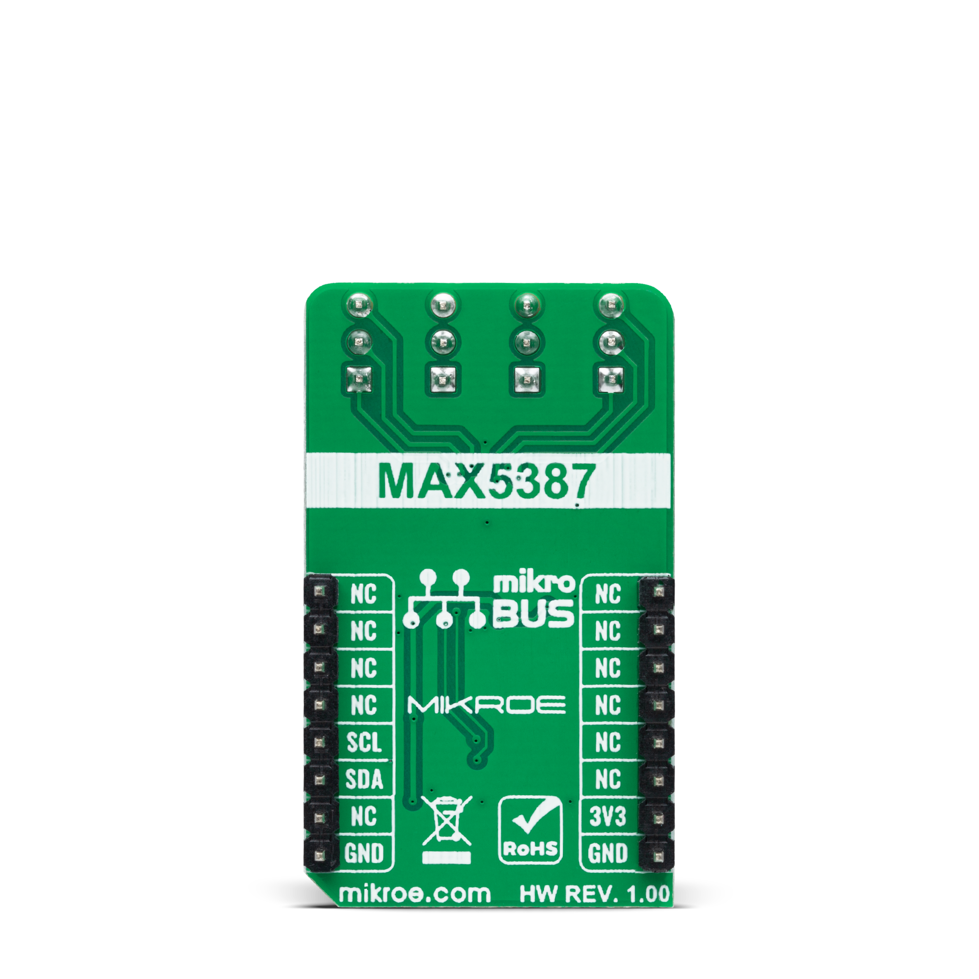
DIGI POT 11 Click
Dev. board
Curiosity Nano with PIC18F57Q43
Compiler
NECTO Studio
MCU
PIC18F57Q43
Electronic replacement for mechanical potentiometer
A
A
Hardware Overview
How does it work?
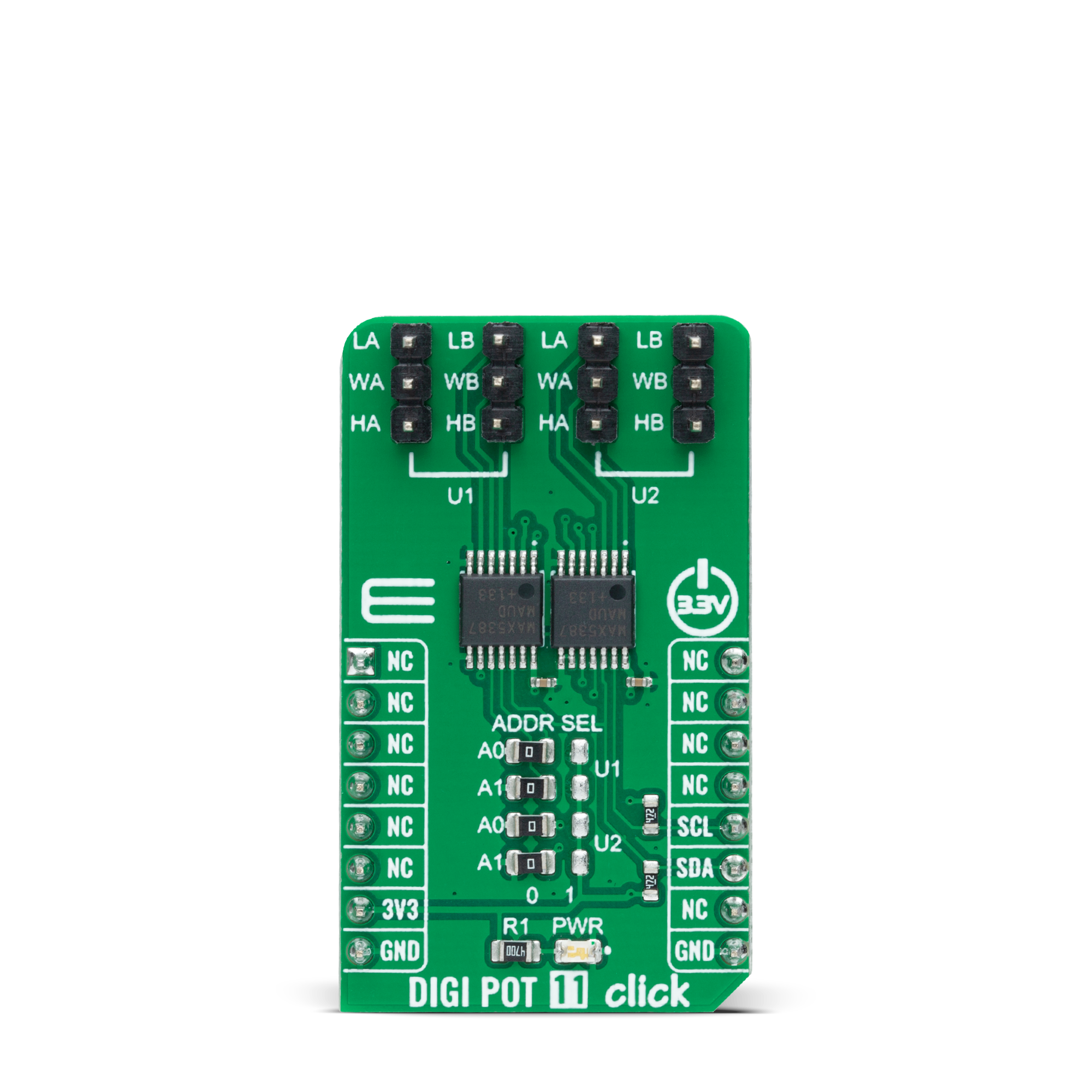
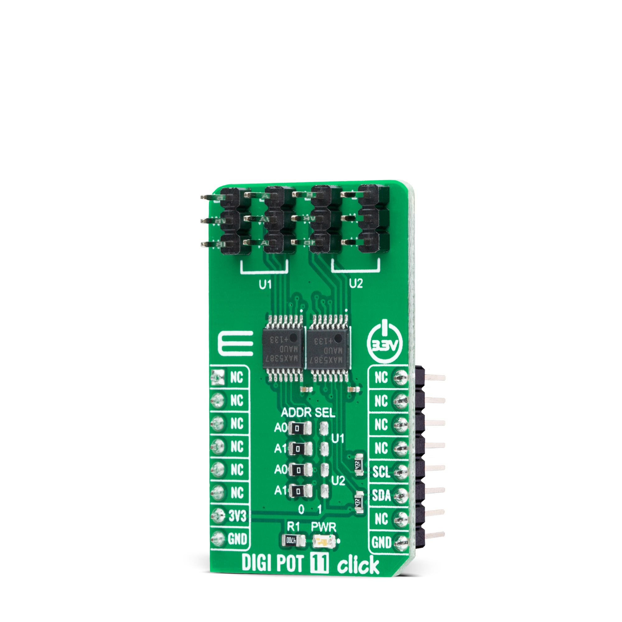
DIGI POT 11 Click is based on a double pack of the MAX5387, a dual volatile, low-voltage linear taper digital potentiometer from Analog Devices. This Click board™ provides four digitally controlled potentiometers realized with an end-to-end resistance value of 50kΩ. The potentiometers have 255 fixed resistors in series between appropriate H and L terminals, providing a low 35ppm/ºC end-to-end temperature coefficient. The potentiometer wiper (W) terminals are programmable to access any one of the 256 tap points on the resistor string. This Click board™ communicates with the host MCU using
the standard I2C 2-Wire interface with a maximum clock frequency of 400kHz. The potentiometers are programmable independently of each other. The MAX5387 has a 7-bit slave address with the first five MSBs fixed to 01010. The address pins A0 and A1 of both potentiometers are programmed by the user and determine the value of the last three LSBs of the slave address, which can be selected by positioning onboard SMD jumpers labeled as ADDR SEL, in U1 or U2 part, to an appropriate position marked as 0 or 1. The I2C interface contains a shift register that decodes the command and addresses bytes, routing the data
to the appropriate control registers. Data written to a control register immediately updates the wiper position. In the beginning, wipers A and B always power up in mid-position. This Click board™ can only be operated from a 3.3V logic voltage level. Therefore, the board must perform appropriate logic voltage conversion before using MCUs with different logic levels. However, the Click board™ comes equipped with a library containing functions and an example code that can be used as a reference for further development.
Features overview
Development board
PIC18F57Q43 Curiosity Nano evaluation kit is a cutting-edge hardware platform designed to evaluate microcontrollers within the PIC18-Q43 family. Central to its design is the inclusion of the powerful PIC18F57Q43 microcontroller (MCU), offering advanced functionalities and robust performance. Key features of this evaluation kit include a yellow user LED and a responsive
mechanical user switch, providing seamless interaction and testing. The provision for a 32.768kHz crystal footprint ensures precision timing capabilities. With an onboard debugger boasting a green power and status LED, programming and debugging become intuitive and efficient. Further enhancing its utility is the Virtual serial port (CDC) and a debug GPIO channel (DGI
GPIO), offering extensive connectivity options. Powered via USB, this kit boasts an adjustable target voltage feature facilitated by the MIC5353 LDO regulator, ensuring stable operation with an output voltage ranging from 1.8V to 5.1V, with a maximum output current of 500mA, subject to ambient temperature and voltage constraints.

Microcontroller Overview
MCU Card / MCU

Architecture
PIC
MCU Memory (KB)
128
Silicon Vendor
Microchip
Pin count
48
RAM (Bytes)
8196
You complete me!
Accessories
Curiosity Nano Base for Click boards is a versatile hardware extension platform created to streamline the integration between Curiosity Nano kits and extension boards, tailored explicitly for the mikroBUS™-standardized Click boards and Xplained Pro extension boards. This innovative base board (shield) offers seamless connectivity and expansion possibilities, simplifying experimentation and development. Key features include USB power compatibility from the Curiosity Nano kit, alongside an alternative external power input option for enhanced flexibility. The onboard Li-Ion/LiPo charger and management circuit ensure smooth operation for battery-powered applications, simplifying usage and management. Moreover, the base incorporates a fixed 3.3V PSU dedicated to target and mikroBUS™ power rails, alongside a fixed 5.0V boost converter catering to 5V power rails of mikroBUS™ sockets, providing stable power delivery for various connected devices.

Used MCU Pins
mikroBUS™ mapper
Take a closer look
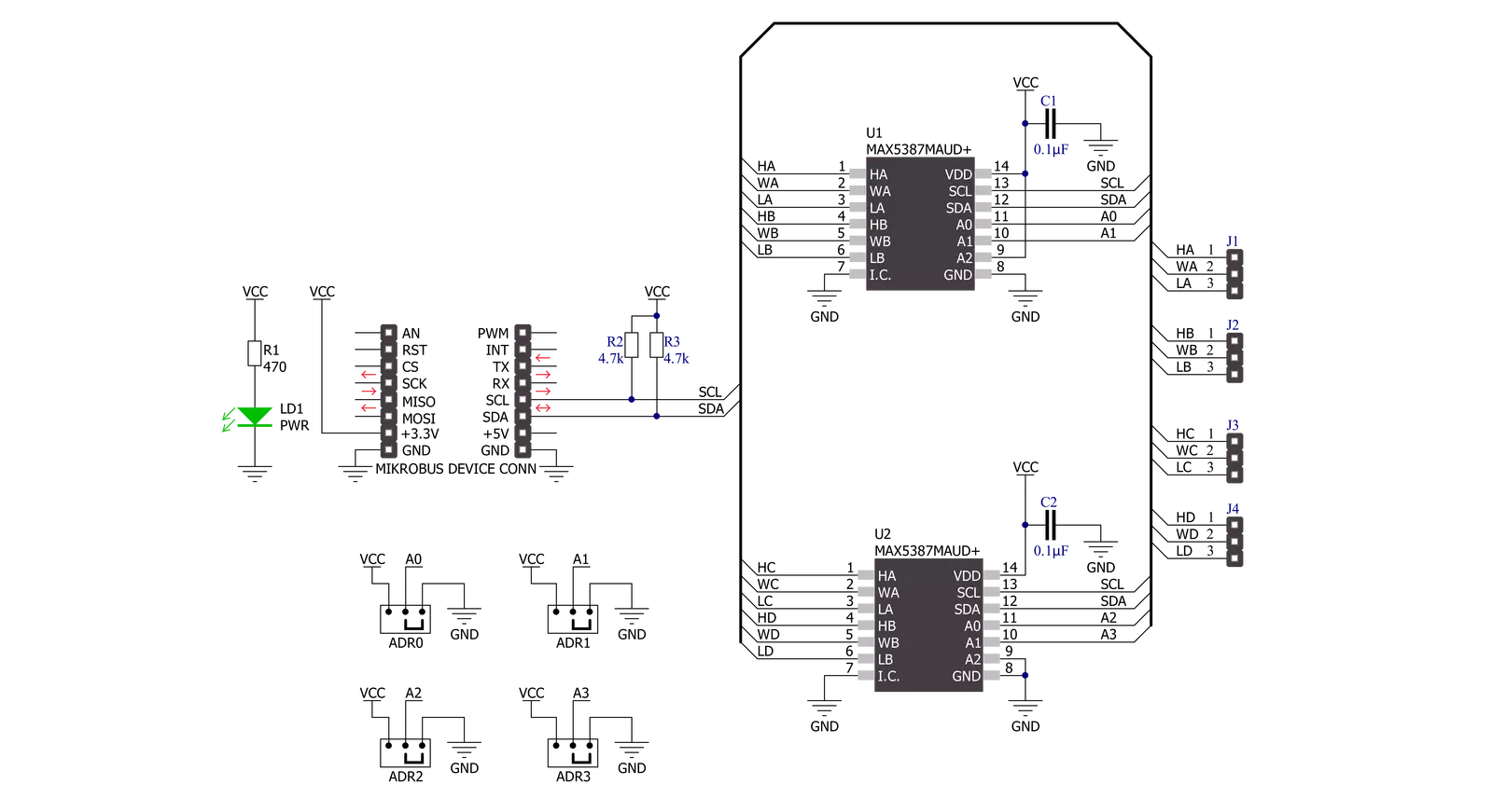
Click board™ Schematic
Step by step
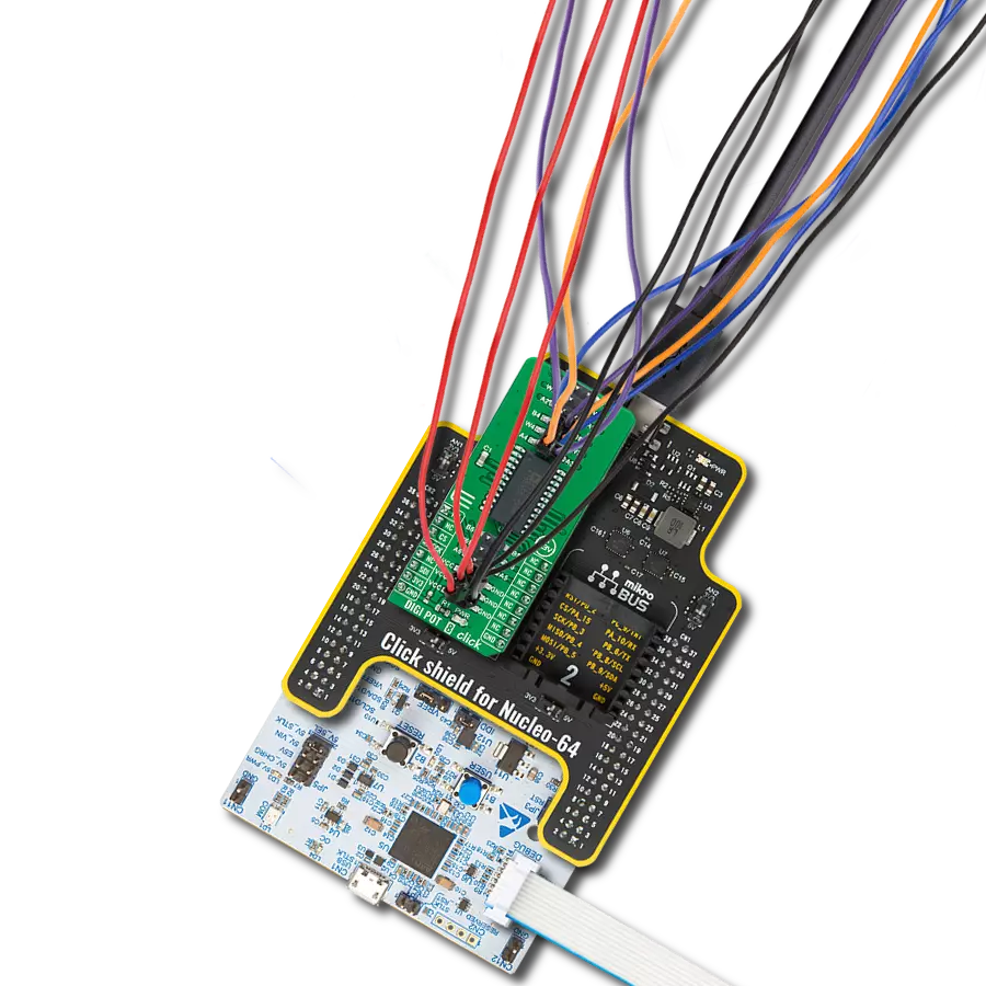
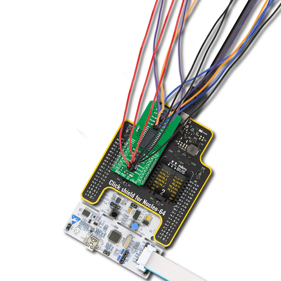
Project assembly

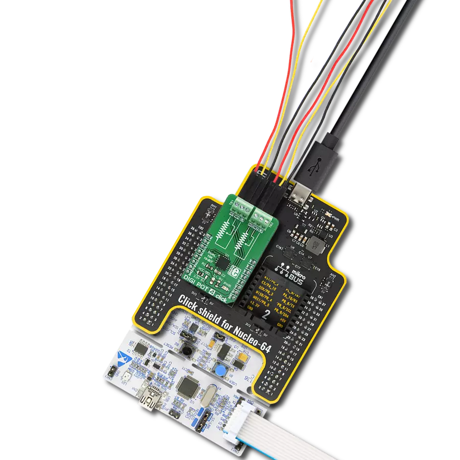
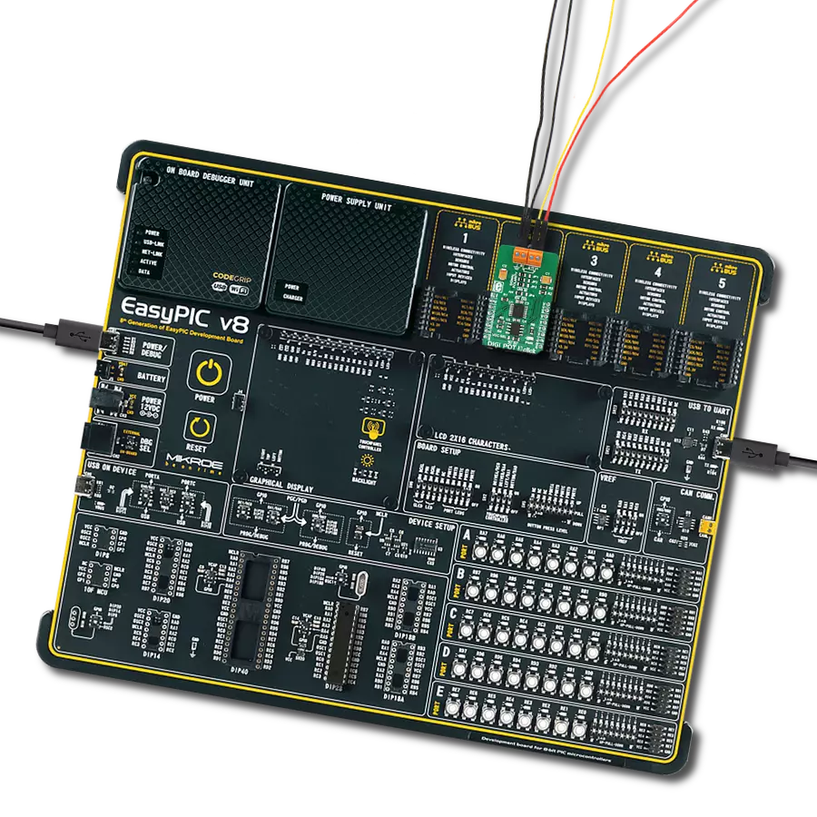
Start by selecting your development board and Click board™. Begin with the Curiosity Nano with PIC18F57Q43 as your development board.


Software Support
Library Description
This library contains API for DIGI POT 11 Click driver.
Key functions:
digipot11_set_u1_wiperThis function sets the position of the selected wiper of U1 device by using I2C serial interface.digipot11_set_u2_wiperThis function sets the position of the selected wiper of U2 device by using I2C serial interface.
Open Source
Code example
The complete application code and a ready-to-use project are available through the NECTO Studio Package Manager for direct installation in the NECTO Studio. The application code can also be found on the MIKROE GitHub account.
/*!
 * @file main.c
 * @brief DIGI POT 11 Click example
 *
 * # Description
 * This example demonstrates the use of DIGI POT 11 Click board by changing
 * the wipers position of both U1 and U2 devices.
 *
 * The demo application is composed of two sections :
 *
 * ## Application Init
 * Initializes the driver and logger.
 *
 * ## Application Task
 * Iterates through the entire wiper range and sets the wipers position of
 * both U1 and U2 devices once per second. The current wiper position will
 * be displayed on the USB UART.
 *
 * @author Stefan Filipovic
 *
 */

#include "board.h"
#include "log.h"
#include "digipot11.h"

static digipot11_t digipot11;
static log_t logger;

void application_init ( void )
{
    log_cfg_t log_cfg;  /**< Logger config object. */
    digipot11_cfg_t digipot11_cfg;  /**< Click config object. */

    /**
     * Logger initialization.
     * Default baud rate: 115200
     * Default log level: LOG_LEVEL_DEBUG
     * @note If USB_UART_RX and USB_UART_TX
     * are defined as HAL_PIN_NC, you will
     * need to define them manually for log to work.
     * See @b LOG_MAP_USB_UART macro definition for detailed explanation.
     */
    LOG_MAP_USB_UART( log_cfg );
    log_init( &logger, &log_cfg );
    log_info( &logger, " Application Init " );

    // Click initialization.
    digipot11_cfg_setup( &digipot11_cfg );
    DIGIPOT11_MAP_MIKROBUS( digipot11_cfg, MIKROBUS_1 );
    if ( I2C_MASTER_ERROR == digipot11_init( &digipot11, &digipot11_cfg ) )
    {
        log_error( &logger, " Communication init." );
        for ( ; ; );
    }

    log_info( &logger, " Application Task " );
}

void application_task ( void )
{
    for ( uint16_t wiper_pos = DIGIPOT11_WIPER_ZERO_SCALE; wiper_pos <= DIGIPOT11_WIPER_FULL_SCALE; wiper_pos += 5 )
    {
        if ( DIGIPOT11_OK == digipot11_set_u1_wiper ( &digipot11, DIGIPOT11_WIPER_SEL_BOTH, ( uint8_t ) wiper_pos ) )
        {
            log_printf( &logger, " U1 wipers position: %u\r\n", wiper_pos );
        }
        if ( DIGIPOT11_OK == digipot11_set_u2_wiper ( &digipot11, DIGIPOT11_WIPER_SEL_BOTH,
                                                      ( uint8_t ) ( DIGIPOT11_WIPER_FULL_SCALE - wiper_pos ) ) )
        {
            log_printf( &logger, " U2 wipers position: %u\r\n\n", ( DIGIPOT11_WIPER_FULL_SCALE - wiper_pos ) );
        }
        Delay_ms ( 1000 );
    }
}

int main ( void )
{
    /* Do not remove this line or clock might not be set correctly. */
    #ifdef PREINIT_SUPPORTED
    preinit();
    #endif

    application_init( );

    for ( ; ; )
    {
        application_task( );
    }

    return 0;
}

// ------------------------------------------------------------------------ END
Additional Support
Resources
Category:Digital potentiometer