Achieve accurate and reliable line tracking with QRE1113 and PIC18F57Q43
On the right track: Elevate your app's capabilities

Published Feb 13, 2024
Click board™
Line Follower Click
Dev. board
Curiosity Nano with PIC18F57Q43
Compiler
NECTO Studio
MCU
PIC18F57Q43
Seamlessly integrate line following into your application to enhance automation processes, improving efficiency and reducing errors
A
A
Hardware Overview
How does it work?
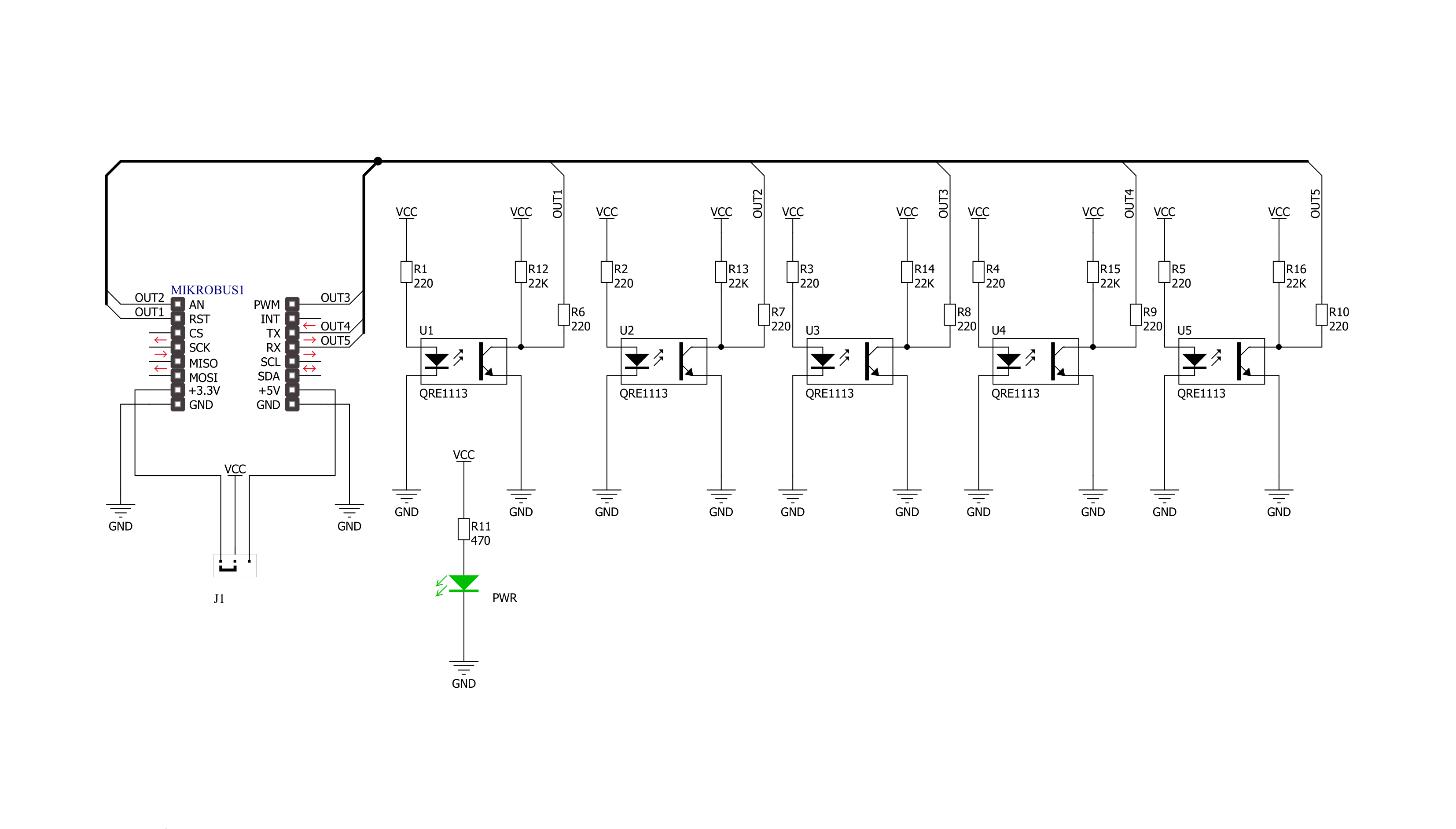
Line Follower Click is based on the QRE1113, a miniature reflective object sensor from ON Semiconductor. The array of the QRE1113 sensors is close to each other and points in the same direction, thus covering the more expansive space completely. The QRE1113 sensor is a no-surface contact sensing device and uses a phototransistor for output. By default, the sensor outputs a high logic level until it encounters a white surface, which changes the output signal to a low
logic state. Since there are five adjacent sensors, you can deduce the position or thickness of the white line from the combination of their outputs. The best results this Click board™ achieves are at a few millimeters from the surface to the sensors. The Line Follower Click communicates with the host MCU by sending logical states to the corresponding pins of the mikroBUS™ socket. Each QRE1113 sensor has its own digital output; each routed through a single mikroBUS™ pin: U1,
U2, U3, U4, and U5 (in place of default mikroBUS™ pins RST, AN, PWM, RX, and TX, respectively). This Click board™ can operate with either 3.3V or 5V logic voltage levels selected via the PWR SEL jumper. This way, both 3.3V and 5V capable MCUs can use the communication lines properly. Also, this Click board™ comes equipped with a library containing easy-to-use functions and an example code that can be used as a reference for further development.

Features overview
Development board
PIC18F57Q43 Curiosity Nano evaluation kit is a cutting-edge hardware platform designed to evaluate microcontrollers within the PIC18-Q43 family. Central to its design is the inclusion of the powerful PIC18F57Q43 microcontroller (MCU), offering advanced functionalities and robust performance. Key features of this evaluation kit include a yellow user LED and a responsive
mechanical user switch, providing seamless interaction and testing. The provision for a 32.768kHz crystal footprint ensures precision timing capabilities. With an onboard debugger boasting a green power and status LED, programming and debugging become intuitive and efficient. Further enhancing its utility is the Virtual serial port (CDC) and a debug GPIO channel (DGI
GPIO), offering extensive connectivity options. Powered via USB, this kit boasts an adjustable target voltage feature facilitated by the MIC5353 LDO regulator, ensuring stable operation with an output voltage ranging from 1.8V to 5.1V, with a maximum output current of 500mA, subject to ambient temperature and voltage constraints.

Microcontroller Overview
MCU Card / MCU

Architecture
PIC
MCU Memory (KB)
128
Silicon Vendor
Microchip
Pin count
48
RAM (Bytes)
8196
You complete me!
Accessories
Curiosity Nano Base for Click boards is a versatile hardware extension platform created to streamline the integration between Curiosity Nano kits and extension boards, tailored explicitly for the mikroBUS™-standardized Click boards and Xplained Pro extension boards. This innovative base board (shield) offers seamless connectivity and expansion possibilities, simplifying experimentation and development. Key features include USB power compatibility from the Curiosity Nano kit, alongside an alternative external power input option for enhanced flexibility. The onboard Li-Ion/LiPo charger and management circuit ensure smooth operation for battery-powered applications, simplifying usage and management. Moreover, the base incorporates a fixed 3.3V PSU dedicated to target and mikroBUS™ power rails, alongside a fixed 5.0V boost converter catering to 5V power rails of mikroBUS™ sockets, providing stable power delivery for various connected devices.

Used MCU Pins
mikroBUS™ mapper
Take a closer look
Click board™ Schematic
Step by step
Project assembly

Start by selecting your development board and Click board™. Begin with the Curiosity Nano with PIC18F57Q43 as your development board.


Software Support
Library Description
This library contains API for Line Follower Click driver.
Key functions:
linefollower_data_track- Get status of all pin function
Open Source
Code example
The complete application code and a ready-to-use project are available through the NECTO Studio Package Manager for direct installation in the NECTO Studio. The application code can also be found on the MIKROE GitHub account.
/*!
 * \file
 * \brief Line Follower Click example
 *
 * # Description
 * Line Follower Click carries an array of five QRE1113
 * miniature reflective object sensors,
 * reading staus of AN, RST, PWM, TX and RX pins and reading tracking data.
 *
 * The demo application is composed of two sections :
 *
 * ## Application Init
 * Application Init performs logger and Click Initialization.
 *
 * ## Application Task
 * Application Task shows the functionality of the Line Follower Click.
 * Each one of the QRE1113 sensors consist of an
 * infrared transmitter and infrared receiver.
 * By default the sensor output a Logic Level 1, until they encounter a
 * white surface which changes the output signal to 0.
 *
 * \author Nenad Filipovic
 *
 */
// ------------------------------------------------------------------- INCLUDES

#include "board.h"
#include "log.h"
#include "linefollower.h"

// ------------------------------------------------------------------ VARIABLES

static linefollower_t linefollower;
static log_t logger;

// ------------------------------------------------------ APPLICATION FUNCTIONS

void application_init ( void )
{
    log_cfg_t log_cfg;
    linefollower_cfg_t cfg;

    /**
     * Logger initialization.
     * Default baud rate: 115200
     * Default log level: LOG_LEVEL_DEBUG
     * @note If USB_UART_RX and USB_UART_TX
     * are defined as HAL_PIN_NC, you will
     * need to define them manually for log to work.
     * See @b LOG_MAP_USB_UART macro definition for detailed explanation.
     */
    LOG_MAP_USB_UART( log_cfg );
    log_init( &logger, &log_cfg );
    log_printf( &logger, "----------------------\r\n" );
    log_printf( &logger, " - Application Init -\r\n" );

    //  Click initialization.
    linefollower_cfg_setup( &cfg );
    LINEFOLLOWER_MAP_MIKROBUS( cfg, MIKROBUS_1 );
    linefollower_init( &linefollower, &cfg );

    log_printf( &logger, "----------------------\r\n" );
    log_printf( &logger, " Line Follower  Click \r\n" );
    log_printf( &logger, "----------------------\r\n" );
}

void application_task ( void )
{
    linefollower_direction_t data_track;

    linefollower_data_track ( &linefollower, &data_track );

    log_printf( &logger, " %u\t%u\t%u\t%u\t%u\r\n",
                (uint16_t) data_track.u1,
                (uint16_t) data_track.u2,
                (uint16_t) data_track.u3,
                (uint16_t) data_track.u4,
                (uint16_t) data_track.u5);

    Delay_ms ( 100 );
}

int main ( void )
{
    /* Do not remove this line or clock might not be set correctly. */
    #ifdef PREINIT_SUPPORTED
    preinit();
    #endif

    application_init( );

    for ( ; ; )
    {
        application_task( );
    }

    return 0;
}


// ------------------------------------------------------------------------ END
Additional Support
Resources
Category:Optical


