Provide essential functions for charging and managing battery power in electronic devices with nPM1300 and PIC18F57Q43
Advanced Power Management Integrated Circuit (PMIC) for rechargeable applications
Published Aug 21, 2024
Click board™
PMIC Click
Dev. board
Curiosity Nano with PIC18F57Q43
Compiler
NECTO Studio
MCU
PIC18F57Q43
Optimize battery life and performance in IoT applications and other portable electronics ensuring longer operation times
A
A
Hardware Overview
How does it work?
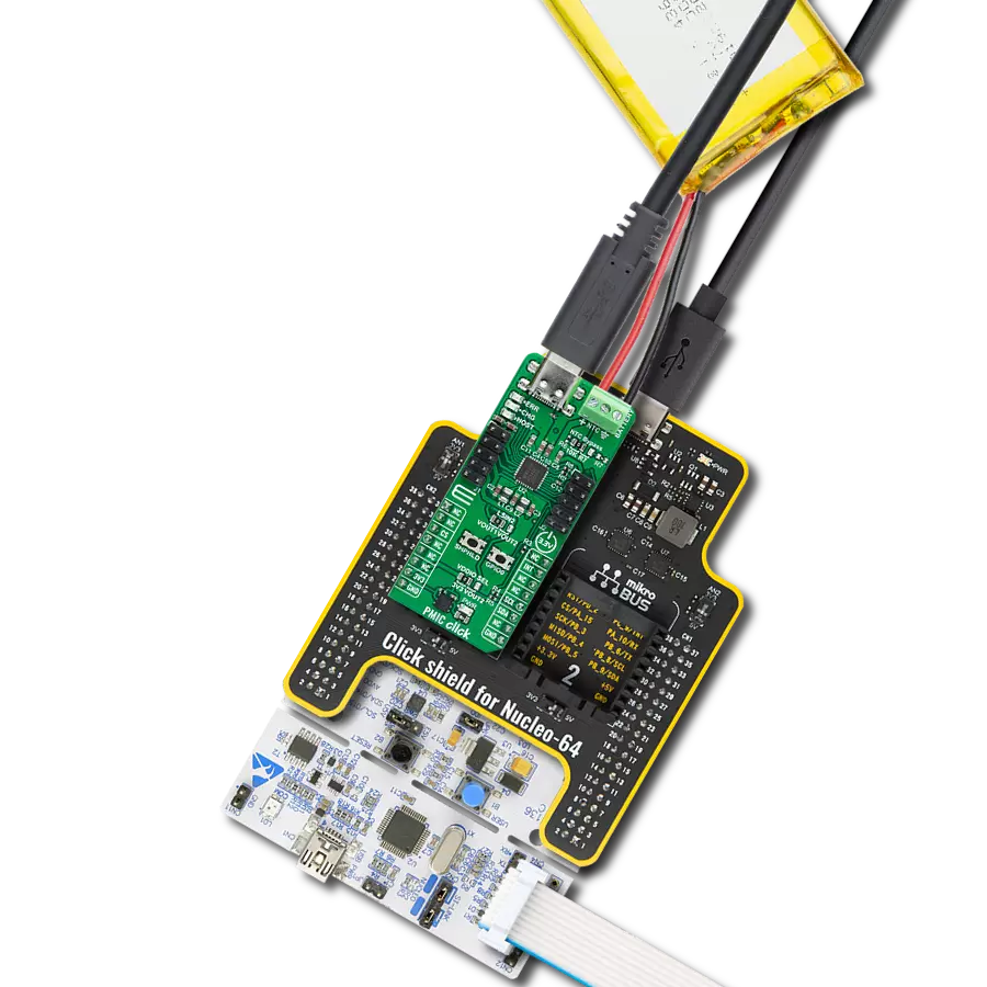
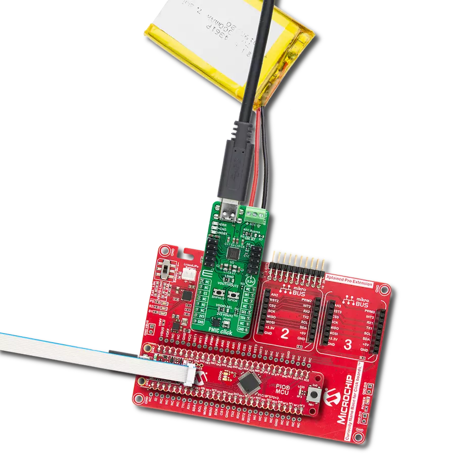
PMIC Click is based on the nPM1300, an advanced Power Management Integrated Circuit (PMIC) from Nordic Semiconductor designed for rechargeable applications. The nPM1300 integrates a variety of power and system management functionalities, offering a compact and efficient solution for managing power in devices. It supports battery charging for lithium-ion (Li-ion), lithium-polymer (Li-poly), and lithium iron phosphate (LiFePO4) batteries, using a flexible power regulation system. Housed in a space-saving QFN32 package, the nPM1300 is made for high efficiency and is fully configurable via an I2C interface, making it ideal for wearables, peripherals, asset tracking, interactive entertainment, IoT applications, and much more. The nPM1300 features an integrated 800mA linear battery charger that ensures safe and efficient charging by adhering to the JEITA standards, which adjusts the charging process based on temperature to protect the battery and extend its lifespan. A battery can be connected to a connector in the upper right corner that supports the integration of an NTC thermistor for precise battery temperature monitoring. If the used battery pack already includes an NTC, the NTC terminal on the BATTERY connector can be left unconnected. For scenarios where a battery without an NTC thermistor is used, the board provides options to bypass this requirement by using onboard resistors. An integrated 10K resistor is available by default, or you can customize the value via an empty resistor footprint (R7 0603) to match specific needs. This feature can be selected via an onboard NTC Bypass jumper. Besides the battery charger, the nPM1300 also integrates two 200mA buck regulators and two 100mA load switches or 50mA Low Dropout Regulators (LDOs). These load switches offer flexibility in managing power distribution across your device. Control of these load switches is achieved through I2C registers or GPIO pins, providing flexibility to tailor the power
configuration to your application's requirements. A notable feature is the ability to select the input source for a second load switch via the LSIN2 jumper, allowing you to choose between the output voltage of one of the buck regulators (VOUT1 or VOUT2). The regulated outputs, VOUT1 and VOUT2, are currently configured to output 1.8V, and VOUT2 is set to 3.3V. These configurations are achieved through specific resistor settings - R8 for VOUT1 and R9 for VOUT2, where VOUT1 can be adjusted within a range of 0V to 2.7V, while VOUT2 from 0V to 3.3V, depending on the selected resistor values. Unregulated output VBUSOUT is directly tied to the VBUS input, offering an unregulated power source that can be used for additional system needs, while VSYS serves as another unregulated output derived from the system's overall power supply. The primary power supply for the nPM1300 PMIC is provided by the VBUS connection, which is a dedicated USB Type-C input. Alongside VBUS, the complementary power supply is VBAT, which also acts as the output for the battery charger, ensuring that the connected battery is charged while maintaining a stable power supply to the system. In addition, the nPM1300 also enhances system reliability with a watchdog that resets the system if it becomes unresponsive, failed-boot recovery for system integrity, and an intelligent power-loss warning to prevent data loss or failure. PMIC Click uses a standard 2-wire I2C interface for communication with the host MCU, supporting a clock frequency of up to 400kHz in Standard mode. Besides interface pins, the board also features an interrupt (INT) pin providing real-time alerts to the host system for immediate action. To manage the power states, PMIC Click includes a SHPHLD button to exit Ship and Hibernation mode - two of the lowest quiescent current states available. These modes disconnect the battery from the system, reducing the quiescent current to extend the battery life. Hibernate mode, in
particular, can be used during normal operation, as the device can automatically wake up after a preconfigured timeout, maximizing battery efficiency. The SHPHLD button also allows users to reset or power cycle the nPM1300. For additional control, the board is equipped with a GPIO0 button, which directly manages the nPM1300's GPIO0 pin. Three LED indicators provide visual feedback: a red ERR LED that signals errors during operation, a green CHG LED that indicates the charging status, and a yellow HOST LED that shows host activity. These LEDs offer clear and immediate visual cues, making monitoring the board's status and troubleshooting any issues easier. Two headers, J1 and J2, provide easy access to power and control functions. The J1 header grants access to the PMIC's voltage outputs, VOUT1 and VOUT2, as well as the USB VBUS voltage through the VBUS pin and VBUSOUT from the nPM1300, allowing you to power external devices directly from the main IC. The J2 header serves multiple purposes, primarily enabling connections to PMIC GPIO pins located in the right column. These GPIOs, configured as inputs with weak pull-downs by default, can be used for custom workflows, standard GPIO functions, or as control pins for the board's buck regulators and load switches. Additionally, the J2 header supports connections for external LEDs and includes the previously mentioned VSYS pin, a system voltage output. This Click board™ can operate with either 3.3V or 3.3V provided from VOUT2 regulated PMIC output selected via the VDDIO SEL jumper. This way, both 3.3V and 5V capable MCUs can use the communication lines properly. Also, this Click board™ comes equipped with a library containing easy-to-use functions and an example code that can be used as a reference for further development.

Features overview
Development board
PIC18F57Q43 Curiosity Nano evaluation kit is a cutting-edge hardware platform designed to evaluate microcontrollers within the PIC18-Q43 family. Central to its design is the inclusion of the powerful PIC18F57Q43 microcontroller (MCU), offering advanced functionalities and robust performance. Key features of this evaluation kit include a yellow user LED and a responsive
mechanical user switch, providing seamless interaction and testing. The provision for a 32.768kHz crystal footprint ensures precision timing capabilities. With an onboard debugger boasting a green power and status LED, programming and debugging become intuitive and efficient. Further enhancing its utility is the Virtual serial port (CDC) and a debug GPIO channel (DGI
GPIO), offering extensive connectivity options. Powered via USB, this kit boasts an adjustable target voltage feature facilitated by the MIC5353 LDO regulator, ensuring stable operation with an output voltage ranging from 1.8V to 5.1V, with a maximum output current of 500mA, subject to ambient temperature and voltage constraints.

Microcontroller Overview
MCU Card / MCU

Architecture
PIC
MCU Memory (KB)
128
Silicon Vendor
Microchip
Pin count
48
RAM (Bytes)
8196
You complete me!
Accessories
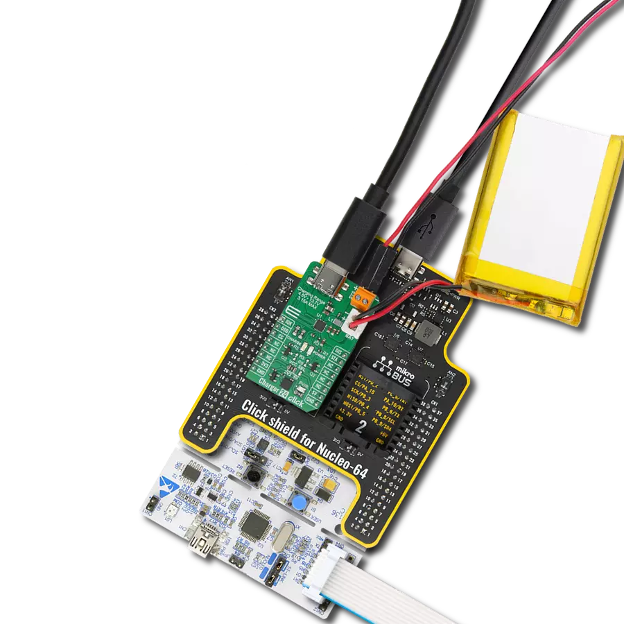
Curiosity Nano Base for Click boards is a versatile hardware extension platform created to streamline the integration between Curiosity Nano kits and extension boards, tailored explicitly for the mikroBUS™-standardized Click boards and Xplained Pro extension boards. This innovative base board (shield) offers seamless connectivity and expansion possibilities, simplifying experimentation and development. Key features include USB power compatibility from the Curiosity Nano kit, alongside an alternative external power input option for enhanced flexibility. The onboard Li-Ion/LiPo charger and management circuit ensure smooth operation for battery-powered applications, simplifying usage and management. Moreover, the base incorporates a fixed 3.3V PSU dedicated to target and mikroBUS™ power rails, alongside a fixed 5.0V boost converter catering to 5V power rails of mikroBUS™ sockets, providing stable power delivery for various connected devices.

Li-Polymer Battery is the ideal solution for devices that demand a dependable and long-lasting power supply while emphasizing mobility. Its compatibility with mikromedia boards ensures easy integration without additional modifications. With a voltage output of 3.7V, the battery meets the standard requirements of many electronic devices. Additionally, boasting a capacity of 2000mAh, it can store a substantial amount of energy, providing sustained power for extended periods. This feature minimizes the need for frequent recharging or replacement. Overall, the Li-Polymer Battery is a reliable and autonomous power source, ideally suited for devices requiring a stable and enduring energy solution.

This is a USB 3.1 cable with USB Type C male connectors on both sides. Cable comes with USB Type C Female to USB Type A Male adapter, making it compabitle with USB 2.0 and USB 3.0 host slots as well. Cable is 1.5 meters long and compatible with any USB type C development tools.

Used MCU Pins
mikroBUS™ mapper
Take a closer look
Click board™ Schematic

Step by step
Project assembly

Start by selecting your development board and Click board™. Begin with the Curiosity Nano with PIC18F57Q43 as your development board.


Software Support
Library Description
This library contains API for PMIC Click driver.
Key functions:
pmic_get_vbat- This function reads the VBAT measurement results in millivolts.pmic_get_vbus- This function reads the VBUS measurement results in millivolts.pmic_get_vsys- This function reads the VSYS measurement results in millivolts.
Open Source
Code example
The complete application code and a ready-to-use project are available through the NECTO Studio Package Manager for direct installation in the NECTO Studio. The application code can also be found on the MIKROE GitHub account.
/*!
 * @file main.c
 * @brief PMIC Click example
 *
 * # Description
 * This example demonstrates the use of PMIC Click board by enabling battery charging and
 * displaying the charging status.
 *
 * The demo application is composed of two sections :
 *
 * ## Application Init
 * Initializes the driver and performs the Click default configuration which enables charging.
 *
 * ## Application Task
 * Reads and displays the VBAT, VBUS, and VSYS voltage and the battery charging status on the USB UART
 * approximately once per second.
 *
 * @note
 * A charged battery or a USB at VBUS must be connected to communicate with the Click board.
 *
 * @author Stefan Filipovic
 *
 */

#include "board.h"
#include "log.h"
#include "pmic.h"

static pmic_t pmic;
static log_t logger;

/**
 * @brief PMIC display charger status function.
 * @details This function reads and parses the battery charger status register.
 * @param[in] ctx : Click context object.
 * See #pmic_t object definition for detailed explanation.
 * @return None.
 * @note None.
 */
void pmic_display_charger_status ( pmic_t *ctx );

void application_init ( void )
{
    log_cfg_t log_cfg;  /**< Logger config object. */
    pmic_cfg_t pmic_cfg;  /**< Click config object. */

    /**
     * Logger initialization.
     * Default baud rate: 115200
     * Default log level: LOG_LEVEL_DEBUG
     * @note If USB_UART_RX and USB_UART_TX
     * are defined as HAL_PIN_NC, you will
     * need to define them manually for log to work.
     * See @b LOG_MAP_USB_UART macro definition for detailed explanation.
     */
    LOG_MAP_USB_UART( log_cfg );
    log_init( &logger, &log_cfg );
    log_info( &logger, " Application Init " );

    // Click initialization.
    pmic_cfg_setup( &pmic_cfg );
    PMIC_MAP_MIKROBUS( pmic_cfg, MIKROBUS_1 );
    if ( I2C_MASTER_ERROR == pmic_init( &pmic, &pmic_cfg ) )
    {
        log_error( &logger, " Communication init." );
        for ( ; ; );
    }

    if ( PMIC_ERROR == pmic_default_cfg ( &pmic ) )
    {
        log_error( &logger, " Default configuration." );
        for ( ; ; );
    }

    log_info( &logger, " Application Task " );
}

void application_task ( void )
{
    uint16_t vbat = 0, vbus = 0, vsys = 0;
    if ( PMIC_OK == pmic_get_vbat ( &pmic, &vbat ) )
    {
        log_printf( &logger, " VBAT : %u mV\r\n", vbat );
    }
    if ( PMIC_OK == pmic_get_vbus ( &pmic, &vbus ) )
    {
        log_printf( &logger, " VBUS : %u mV\r\n", vbus );
    }
    if ( PMIC_OK == pmic_get_vsys ( &pmic, &vsys ) )
    {
        log_printf( &logger, " VSYS : %u mV\r\n\n", vsys );
    }
    pmic_display_charger_status ( &pmic );
    Delay_ms ( 1000 );
}

int main ( void )
{
    /* Do not remove this line or clock might not be set correctly. */
    #ifdef PREINIT_SUPPORTED
    preinit();
    #endif

    application_init( );

    for ( ; ; )
    {
        application_task( );
    }

    return 0;
}

void pmic_display_charger_status ( pmic_t *ctx )
{
    uint8_t charge_status = 0;
    if ( PMIC_OK == pmic_reg_read_byte ( &pmic, PMIC_REG_BCHARGER_BCHGCHARGESTATUS, &charge_status ) )
    {
        log_printf( &logger, " --- Battery Charge status ---\r\n" );
        if ( charge_status & PMIC_CHARGE_STATUS_BATTERYDETECTED )
        {
            log_printf( &logger, " Battery is connected\r\n" );
        }
        if ( charge_status & PMIC_CHARGE_STATUS_COMPLETED )
        {
            log_printf( &logger, " Charging completed (Battery Full)\r\n" );
        }
        if ( charge_status & PMIC_CHARGE_STATUS_TRICKLECHARGE )
        {
            log_printf( &logger, " Trickle charge\r\n" );
        }
        if ( charge_status & PMIC_CHARGE_STATUS_CONSTANTCURRENT )
        {
            log_printf( &logger, " Constant Current charging\r\n" );
        }
        if ( charge_status & PMIC_CHARGE_STATUS_CONSTANTVOLTAGE )
        {
            log_printf( &logger, " Constant Voltage charging\r\n" );
        }
        if ( charge_status & PMIC_CHARGE_STATUS_RECHARGE )
        {
            log_printf( &logger, " Battery re-charge is needed\r\n" );
        }
        if ( charge_status & PMIC_CHARGE_STATUS_DIETEMPHIGHCHGPAUSED )
        {
            log_printf( &logger, " Charging stopped due Die Temp high.\r\n" );
        }
        if ( charge_status & PMIC_CHARGE_STATUS_SUPPLEMENTACTIVE )
        {
            log_printf( &logger, " Supplement Mode Active\r\n" );
        }
        log_printf( &logger, " -----------------------------\r\n" );
    }
}
// ------------------------------------------------------------------------ END
Additional Support
Resources
Category:Battery charger