Ensure seamless data transmission using ADuM341E and PIC18F57Q43
SPI Isolator: The key to reliable data transmission
Published Feb 13, 2024
Click board™
SPI Isolator 4 Click
Dev. board
Curiosity Nano with PIC18F57Q43
Compiler
NECTO Studio
MCU
PIC18F57Q43
This isolator allows you to bridge the gap between systems with different ground references, ensuring that data is transmitted accurately and without disruptions
A
A
Hardware Overview
How does it work?
SPI Isolator 4 Click is based on the ADuM341E, a quad-channel digital isolator optimized for a serial peripheral interface from Analog Devices. This isolation component provides outstanding performance characteristics by combining high-speed and CMOS technology. It uses a high-frequency carrier to transmit data across the isolation barrier using iCoupler chip scale transformer coils separated by layers of polyimide isolation. Its data channels are independent and available in various configurations with a withstand voltage rating of 5kVrms. Using an ON/OFF keying (OOK) technique and the differential architecture, the ADuM341E has a very low propagation delay and high speed. It operates
with the external supply voltage ranging from 2.25V to 5.5V, providing compatibility with lower voltage systems and enabling voltage translation functionality across the isolation barrier. The ADuM341E architecture is designed for high common-mode transient (CMTI) immunity and high immunity to electrical noise and magnetic interference. Unlike other optocoupler alternatives, DC correctness is ensured without input logic transitions. Two different fail-safe options are available, by which the outputs go into a predetermined state when the input power supply is not applied or the inputs are disabled. SPI Isolator 4 Click communicates with an MCU using the SPI serial interface with a maximum data rate
of 100Mbps. This Click board™ also comes with an SDO line enable control pin, labeled as EN1, routed on the PWM pin of the mikroBUS™ socket. When EN1 is in a high logic state, the SDO line is enabled, and when EN1 is in a low logic state, the SDO line is disabled to the high-Z state. This Click board™ can operate with either 3.3V or 5V logic voltage levels selected via the VCC SEL jumper. This way, both 3.3V and 5V capable MCUs can use the communication lines properly. Also, this Click board™ comes equipped with a library containing easy-to-use functions and an example code that can be used as a reference for further development.


Features overview
Development board
PIC18F57Q43 Curiosity Nano evaluation kit is a cutting-edge hardware platform designed to evaluate microcontrollers within the PIC18-Q43 family. Central to its design is the inclusion of the powerful PIC18F57Q43 microcontroller (MCU), offering advanced functionalities and robust performance. Key features of this evaluation kit include a yellow user LED and a responsive
mechanical user switch, providing seamless interaction and testing. The provision for a 32.768kHz crystal footprint ensures precision timing capabilities. With an onboard debugger boasting a green power and status LED, programming and debugging become intuitive and efficient. Further enhancing its utility is the Virtual serial port (CDC) and a debug GPIO channel (DGI
GPIO), offering extensive connectivity options. Powered via USB, this kit boasts an adjustable target voltage feature facilitated by the MIC5353 LDO regulator, ensuring stable operation with an output voltage ranging from 1.8V to 5.1V, with a maximum output current of 500mA, subject to ambient temperature and voltage constraints.

Microcontroller Overview
MCU Card / MCU

Architecture
PIC
MCU Memory (KB)
128
Silicon Vendor
Microchip
Pin count
48
RAM (Bytes)
8196
You complete me!
Accessories
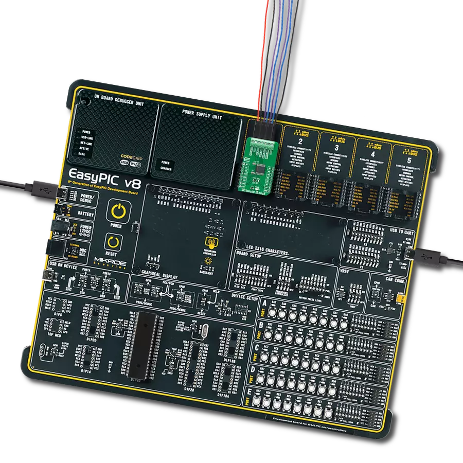
Curiosity Nano Base for Click boards is a versatile hardware extension platform created to streamline the integration between Curiosity Nano kits and extension boards, tailored explicitly for the mikroBUS™-standardized Click boards and Xplained Pro extension boards. This innovative base board (shield) offers seamless connectivity and expansion possibilities, simplifying experimentation and development. Key features include USB power compatibility from the Curiosity Nano kit, alongside an alternative external power input option for enhanced flexibility. The onboard Li-Ion/LiPo charger and management circuit ensure smooth operation for battery-powered applications, simplifying usage and management. Moreover, the base incorporates a fixed 3.3V PSU dedicated to target and mikroBUS™ power rails, alongside a fixed 5.0V boost converter catering to 5V power rails of mikroBUS™ sockets, providing stable power delivery for various connected devices.

Used MCU Pins
mikroBUS™ mapper
Take a closer look
Click board™ Schematic

Step by step
Project assembly

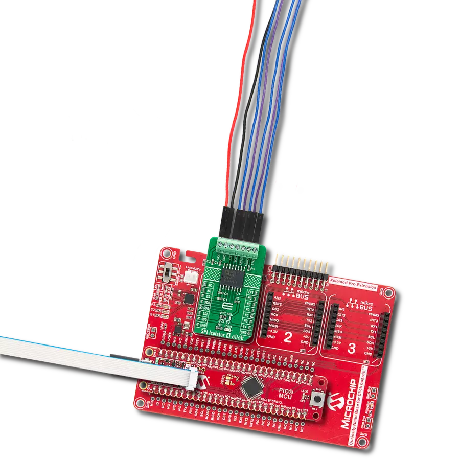
Start by selecting your development board and Click board™. Begin with the Curiosity Nano with PIC18F57Q43 as your development board.


Software Support
Library Description
This library contains API for SPI Isolator 4 Click driver.
Key functions:
spiisolator4_generic_write- SPI Isolator 4 data writing functionspiisolator4_generic_read- SPI Isolator 4 data reading function
Open Source
Code example
The complete application code and a ready-to-use project are available through the NECTO Studio Package Manager for direct installation in the NECTO Studio. The application code can also be found on the MIKROE GitHub account.
/*!
 * @file main.c
 * @brief SPIIsolator4 Click example
 *
 * # Description
 * This library contains API for the SPI Isolator 4 Click driver.
 * This demo application shows an example of an SPI Isolator 4 Click wired
 * to the nvSRAM 4 Click for reading Device ID.
 *
 * The demo application is composed of two sections :
 *
 * ## Application Init
 * Initialization of SPI module and log UART.
 * After driver initialization, the app sets the default configuration.
 *
 * ## Application Task
 * This is an example that shows the use of an SPI Isolator 4 Click board™.
 * Logs Device ID of the nvSRAM 4 Click wired to the SPI Isolator 4 board™.
 * Results are being sent to the Usart Terminal where you can track their changes.
 *
 * ## Additional Function
 * - static void get_device_id ( void )
 *
 * @author Mikroe Team
 *
 */

#include "board.h"
#include "log.h"
#include "spiisolator4.h"

static spiisolator4_t spiisolator4;
static log_t logger;
static uint32_t device_id;

static void get_device_id ( void ) {
    uint8_t rx_data[ 4 ];

    spiisolator4_generic_read( &spiisolator4, 0x9F, &rx_data[ 0 ], 4 );

    device_id = rx_data[ 0 ];
    device_id <<= 8;
    device_id |= rx_data[ 1 ];
    device_id <<= 8;
    device_id |= rx_data[ 2 ];
    device_id <<= 8;
    device_id |= rx_data[ 3 ];
}

void application_init ( void )
{
    log_cfg_t log_cfg;                    /**< Logger config object. */
    spiisolator4_cfg_t spiisolator4_cfg;  /**< Click config object. */

    /**
     * Logger initialization.
     * Default baud rate: 115200
     * Default log level: LOG_LEVEL_DEBUG
     * @note If USB_UART_RX and USB_UART_TX
     * are defined as HAL_PIN_NC, you will
     * need to define them manually for log to work.
     * See @b LOG_MAP_USB_UART macro definition for detailed explanation.
     */
    LOG_MAP_USB_UART( log_cfg );
    log_init( &logger, &log_cfg );
    log_info( &logger, " Application Init " );

    // Click initialization.

    spiisolator4_cfg_setup( &spiisolator4_cfg );
    SPIISOLATOR4_MAP_MIKROBUS( spiisolator4_cfg, MIKROBUS_1 );
    err_t init_flag  = spiisolator4_init( &spiisolator4, &spiisolator4_cfg );
    if ( SPI_MASTER_ERROR == init_flag )
    {
        log_error( &logger, " Application Init Error. " );
        log_info( &logger, " Please, run program again... " );

        for ( ; ; );
    }

    spiisolator4_default_cfg ( &spiisolator4 );
    log_info( &logger, " Application Task " );
    log_printf( &logger, "--------------------------\r\n" );
    Delay_ms ( 100 );
}

void application_task ( void )
{
    get_device_id( );
    log_printf( &logger, "  Device ID : 0x%.8LX\r\n", device_id );
    log_printf( &logger, "--------------------------\r\n" );
    Delay_ms ( 1000 );
}

int main ( void )
{
    /* Do not remove this line or clock might not be set correctly. */
    #ifdef PREINIT_SUPPORTED
    preinit();
    #endif

    application_init( );

    for ( ; ; )
    {
        application_task( );
    }

    return 0;
}

// ------------------------------------------------------------------------ END
Additional Support
Resources
Category:SPI