Enable long-distance data transmission with ease using LTC4332 and STM32F031K6
SPI goes the extra mile: Extending communication for industrial success

Published Oct 01, 2024
Click board™
SPI Extend Click
Dev. board
Nucleo 32 with STM32F031K6 MCU
Compiler
NECTO Studio
MCU
STM32F031K6
Uncover the simplicity and efficiency of our SPI extender solution, providing an accessible and effective means to transmit data over extended distances, transforming the way you connect and communicate
A
A
Hardware Overview
How does it work?
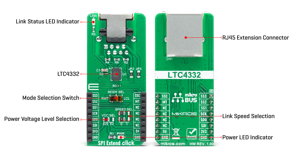
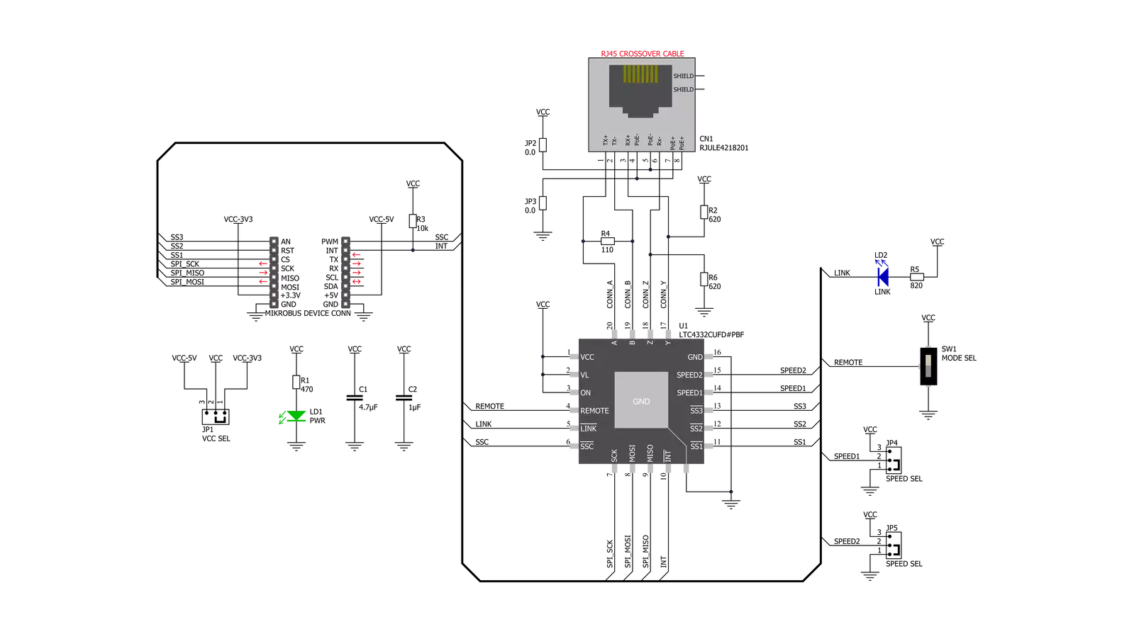
SPI Extend Click is based on LTC4332, a 2MHz point-to-point SPI bus extender designed for operation in high-noise industrial environments, IC from Analog Devices. The SPI bus is extended over two twisted pairs by ±60V fault-protected differential transceivers. The LTC4332’s extended 25V common-mode voltage range allows it to bridge across different ground potentials. This Click board™ has three extended slave selects (SS1, SS2, SS3), has separate programmable SPI modes, and supports external galvanic isolation on the link. Slave select output pin SS1 is used as a standard CS pin in SPI communication, while the other two pins, SS2 and SS3, are used as GPIO output pins on the local side in terms of mikroBUS standard. To achieve the complete functionality of this Click board™, it is necessary to use crossover twisted-pair cables with RJ45 connectors, the same ones used with Ethernet devices. Alongside
its extended functionalities, this Click board™ also supports local to remote control and interrupt functions. Using an integrated high-performance differential transceiver for link communication, a local SPI master can access remote slave devices up to 1200m using differential-pair type cabling. Because of the dual functionality of the SPI Extend Click, the user needs to set the mode of operation of the Click board™, which is adjusted by setting the onboard MODE SEL switch to the appropriate position (set low for local SPI slave mode or set high for SPI master mode). The SPI Extend Click communicates with MCU using the SPI serial interface that supports SPI modes (0,0) and (1,1) only, with a maximum SPI frequency of 2 MHz. The LTC4332 provides a separate slave select pin, SSC, allowing users to access the internal control interface for configuration and monitoring. It also has an interrupt pin (INT) that acts as an
open-drain output in local mode and an input in remote mode. On the remote side, INT is an input pin that can be connected to remote SPI devices, while on the local side, INT operates as an open-drain output that can be connected to a shared local interrupt line. In addition to the mode selection, SPEED SEL jumpers select the link baud rate, and the remote SCK timing parameters, and the Link Status LED indicator is active when the device successfully establishes link communication between the local and remote sides. This Click board™ can operate with either 3.3V or 5V logic voltage levels selected via the VCC SEL jumper. This way, both 3.3V and 5V capable MCUs can use the communication lines properly. Also, this Click board™ comes equipped with a library containing easy-to-use functions and an example code that can be used as a reference for further development.
Features overview
Development board
Nucleo 32 with STM32F031K6 MCU board provides an affordable and flexible platform for experimenting with STM32 microcontrollers in 32-pin packages. Featuring Arduino™ Nano connectivity, it allows easy expansion with specialized shields, while being mbed-enabled for seamless integration with online resources. The
board includes an on-board ST-LINK/V2-1 debugger/programmer, supporting USB reenumeration with three interfaces: Virtual Com port, mass storage, and debug port. It offers a flexible power supply through either USB VBUS or an external source. Additionally, it includes three LEDs (LD1 for USB communication, LD2 for power,
and LD3 as a user LED) and a reset push button. The STM32 Nucleo-32 board is supported by various Integrated Development Environments (IDEs) such as IAR™, Keil®, and GCC-based IDEs like AC6 SW4STM32, making it a versatile tool for developers.

Microcontroller Overview
MCU Card / MCU

Architecture
ARM Cortex-M0
MCU Memory (KB)
32
Silicon Vendor
STMicroelectronics
Pin count
32
RAM (Bytes)
4096
You complete me!
Accessories
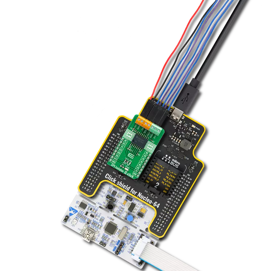
Click Shield for Nucleo-32 is the perfect way to expand your development board's functionalities with STM32 Nucleo-32 pinout. The Click Shield for Nucleo-32 provides two mikroBUS™ sockets to add any functionality from our ever-growing range of Click boards™. We are fully stocked with everything, from sensors and WiFi transceivers to motor control and audio amplifiers. The Click Shield for Nucleo-32 is compatible with the STM32 Nucleo-32 board, providing an affordable and flexible way for users to try out new ideas and quickly create prototypes with any STM32 microcontrollers, choosing from the various combinations of performance, power consumption, and features. The STM32 Nucleo-32 boards do not require any separate probe as they integrate the ST-LINK/V2-1 debugger/programmer and come with the STM32 comprehensive software HAL library and various packaged software examples. This development platform provides users with an effortless and common way to combine the STM32 Nucleo-32 footprint compatible board with their favorite Click boards™ in their upcoming projects.

Used MCU Pins
mikroBUS™ mapper
Take a closer look
Click board™ Schematic
Step by step
Project assembly

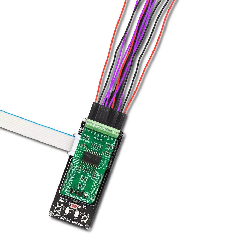
Start by selecting your development board and Click board™. Begin with the Nucleo 32 with STM32F031K6 MCU as your development board.


Software Support
Library Description
This library contains API for SPI Extend Click driver.
Key functions:
spiextend_get_config- Function get configuration of the LTC4332 SPI Extender Over Rugged Differential Link on the SPI Extend Clickspiextend_set_config- Function set configuration of the LTC4332 SPI Extender Over Rugged Differential Link on the SPI Extend Clickspiextend_get_status- Function get status of the LTC4332 SPI Extender Over Rugged Differential Link on the SPI Extend Click
Open Source
Code example
The complete application code and a ready-to-use project are available through the NECTO Studio Package Manager for direct installation in the NECTO Studio. The application code can also be found on the MIKROE GitHub account.
/*!
 * @file main.c
 * @brief SPIExtend Click example
 *
 * # Description
 *  In this example, if the connection is established, we read Accel axis of the connected
 * Accel 14 Click boards to the SPI Extend Click ( Remote Mode ) which is connected by a LAN cable to
 * SPI Extend Click ( Local Mode ) placed in the mikroBUS 1. Results are being sent to the Usart Terminal where you can track their
 * changes. All data logs write on USB uart changes for every 1 sec.
 *
 * The demo application is composed of two sections :
 *
 * ## Application Init
 * Initializes SPI, sets INT pin as input and AN, RST, CS nad PWM pins as outputs and begins to write log.
 * Also, initialization driver enables - SPI, set default configuration of the Accel 14 Click
 * connected to the SPI Extend Click ( Remote Mode ).
 *
 * ## Application Task
 * If the Click is connected properly then the status becomes active and the X-axis coordinate is printed first on the UART terminal,
 * then Y and finally Z. After 1s the process is repeated.
 * In case an error has occurred, printed "LINK is not established" on UART Terminal.
 *
 * Additional Functions :
 *  - void spiextend_accel14_get_axis ( uint8_t axis_out_reg ) - SPI Extend reading axis function.
 *  - void spiextend_display_status ( uint8_t check_status ) - SPI Extend check display status function.
 *
 * @author Jelena Milosavljevic
 *
 */

#include "board.h"
#include "log.h"
#include "spiextend.h"

static spiextend_t spiextend;
static log_t logger;

static int16_t axis;
spiextend_status_data_t spiextend_status;

/**
 * @brief SPI Extend reading axis function.
 * @details This function is used for reading axis.
 * @param[in] axis_out_reg : Data from the register.
 * @return Nothing.
 */
void spiextend_accel14_get_axis ( uint8_t axis_out_reg );

/**
 * @brief SPI Extend check display status function.
 * @details This function is used for check display status.
 * @param[in] check_status : Display data.
 * @return Nothing.
 */
void spiextend_display_status ( uint8_t check_status );

void application_init ( void ) {

    log_cfg_t log_cfg;                /**< Logger config object. */
    spiextend_cfg_t spiextend_cfg;    /**< Click config object. */

    /**
     * Logger initialization.
     * Default baud rate: 115200
     * Default log level: LOG_LEVEL_DEBUG
     * @note If USB_UART_RX and USB_UART_TX
     * are defined as HAL_PIN_NC, you will
     * need to define them manually for log to work.
     * See @b LOG_MAP_USB_UART macro definition for detailed explanation.
     */
    LOG_MAP_USB_UART( log_cfg );
    log_init( &logger, &log_cfg );
    log_info( &logger, " Application Init \r\n" );

    // Click initialization.

    spiextend_cfg_setup( &spiextend_cfg );
    SPIEXTEND_MAP_MIKROBUS( spiextend_cfg, MIKROBUS_1 );
    err_t init_flag  = spiextend_init( &spiextend, &spiextend_cfg );
    if ( SPI_MASTER_ERROR == init_flag ) {

        log_error( &logger, " Application Init Error. \r\n" );
        log_info( &logger, " Please, run program again... \r\n" );

        for ( ; ; );
    }
    spiextend_default_cfg( &spiextend);
    log_printf( &logger, "---------------------\r\n" );
    log_printf( &logger, "   SPI Extend Click  \r\n" );
    log_printf( &logger, "---------------------\r\n" );
    Delay_ms ( 100 );

    spiextend_get_status( &spiextend, &spiextend_status );
    log_printf( &logger, " LINK        : " );

    spiextend_display_status( spiextend_status.nlink );
    log_printf( &logger, " INT         : " );

    spiextend_display_status( spiextend_status.nint );
    log_printf( &logger, " Remote INT  : " );
    spiextend_display_status( spiextend_status.rmt_nint );

    log_printf( &logger, " Speed Index : %d\r\n", ( uint16_t ) spiextend_status.speed_idx );
    log_printf( &logger, "---------------------\r\n" );
    Delay_ms ( 100 );

    log_printf( &logger, "  >>> Accel 14 <<<   \r\n" );
    log_printf( &logger, " Set default config. \r\n" );
    spiextend_rmt_write ( &spiextend, SPIEXTEND_ACCEL14_REG_CTRL1_XL | SPIEXTEND_ACCEL14_SPI_WRITE,
                                      SPIEXTEND_ACCEL14_CTRL1_XL_POWER_UP |
                                      SPIEXTEND_ACCEL14_CTRL1_XL_HIGH_RES_FS |
                                      SPIEXTEND_ACCEL14_CTRL1_XL_GSEL_4G,
                          SPIEXTEND_SLAVE_SELECT_SS1 );
    Delay_ms ( 100 );

    spiextend_rmt_write ( &spiextend, SPIEXTEND_ACCEL14_REG_CTRL3_C | SPIEXTEND_ACCEL14_SPI_WRITE,
                                      SPIEXTEND_ACCEL14_CTRL3_C_BOOT_NORMAL |
                                      SPIEXTEND_ACCEL14_CTRL3_C_BDU_READ_UPDATE |
                                      SPIEXTEND_ACCEL14_CTRL3_C_INT_ACTIVE_HIGH |
                                      SPIEXTEND_ACCEL14_CTRL3_C_PP_OD_PUSH_PULL |
                                      SPIEXTEND_ACCEL14_CTRL3_C_SIM_SPI_4_WIRE |
                                      SPIEXTEND_ACCEL14_CTRL3_C_IF_INC_ENABLE |
                                      SPIEXTEND_ACCEL14_CTRL3_C_SW_RESET_DIS,
                                      SPIEXTEND_SLAVE_SELECT_SS1 );
    Delay_ms ( 100 );

    log_printf( &logger, "---------------------\r\n" );
    log_printf( &logger, "  Acceleration data: \r\n" );
    log_printf( &logger, "---------------------\r\n" );
    Delay_ms ( 100 );

    log_info( &logger, " Application Task \r\n" );
}

void application_task ( void ) {

    //  Task implementation.

    spiextend_get_status( &spiextend, &spiextend_status );

    if ( spiextend_status.nlink == SPIEXTEND_STATUS_ACTIVE ) {

        spiextend_accel14_get_axis( SPIEXTEND_ACCEL14_REG_OUTX_L_A );
        Delay_ms ( 10 );
        log_printf( &logger, "  Accel X : %d \r\n", axis );

        spiextend_accel14_get_axis( SPIEXTEND_ACCEL14_REG_OUTY_L_A );
        Delay_ms ( 10 );
        log_printf( &logger, "  Accel Y : %d \r\n", axis );

        spiextend_accel14_get_axis( SPIEXTEND_ACCEL14_REG_OUTZ_L_A );
        Delay_ms ( 10 );
        log_printf( &logger, "  Accel Z : %d \r\n", axis );

        log_printf( &logger, "---------------------\r\n" );
        Delay_ms ( 1000 );
    }
    else {

        log_printf( &logger, " LINK not established\r\n" );
        log_printf( &logger, "---------------------\r\n" );
        Delay_ms ( 1000 );
    }
}

int main ( void )
{
    /* Do not remove this line or clock might not be set correctly. */
    #ifdef PREINIT_SUPPORTED
    preinit();
    #endif

    application_init( );

    for ( ; ; )
    {
        application_task( );
    }

    return 0;
}

void spiextend_accel14_get_axis ( uint8_t axis_out_reg ) {

    uint16_t rx_val;
    uint8_t lbs;
    uint8_t mbs;

    lbs = spiextend_rmt_read( &spiextend, axis_out_reg| SPIEXTEND_ACCEL14_SPI_READ,
                                                        SPIEXTEND_SLAVE_SELECT_SS1 );

    axis_out_reg++;
    mbs = spiextend_rmt_read( &spiextend, axis_out_reg | SPIEXTEND_ACCEL14_SPI_READ,
                                                         SPIEXTEND_SLAVE_SELECT_SS1 );
    rx_val = mbs;
    rx_val <<= 8;
    rx_val |= lbs;

    axis = ( int16_t ) rx_val;
}

void spiextend_display_status ( uint8_t check_status ) {

    if ( check_status == SPIEXTEND_STATUS_ACTIVE ) {
       log_printf( &logger, " ON \r\n" );
    } else {
        log_printf( &logger, " OFF \r\n" );
    }
}

// ------------------------------------------------------------------------ END
Additional Support
Resources
Category:SPI