Transform your voltage control challenges into triumphs with MAX20406 and PIC18F57Q43
Say goodbye to power wastage and hello to efficiency!

Published Feb 13, 2024
Click board™
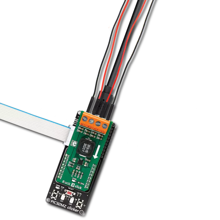
Step Down 9 Click
Dev. board
Curiosity Nano with PIC18F57Q43
Compiler
NECTO Studio
MCU
PIC18F57Q43
Don't just manage voltage, master it! Our synchronous buck converter navigates voltage challenges with precision for optimal power performance.
A
A
Hardware Overview
How does it work?
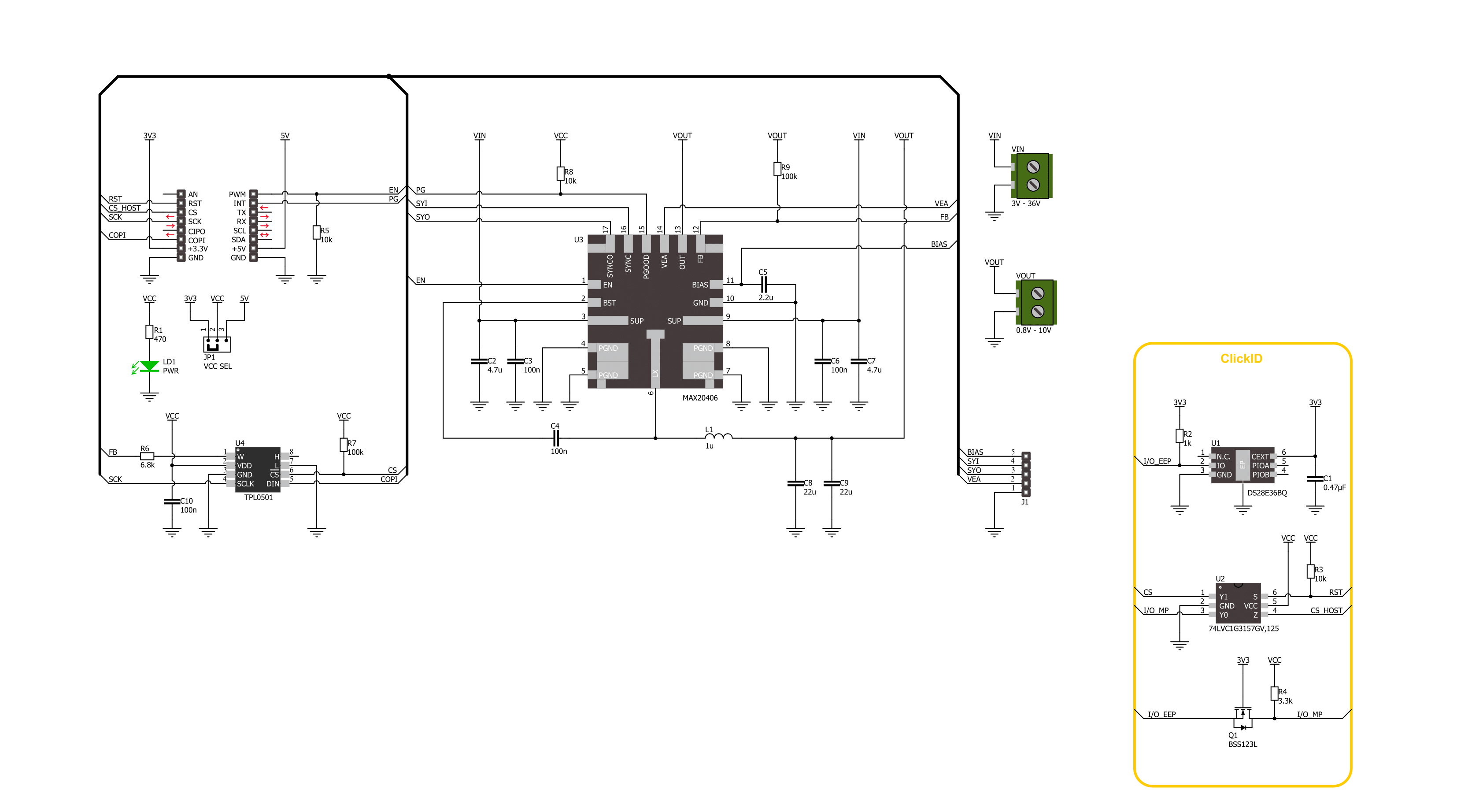
Step Down 9 Click is based on the MAX20406, an automotive fully integrated synchronous silent switcher buck converter from Analog Devices. It is a low EMI emission buck converter with integrated high-side and low-side switches and can operate in dropout by running at a 99% duty cycle. The Step Down 9 Click uses a TPL0501 digital potentiometer in a resistor divider configuration for an external output voltage adjustment. The TPL0501 is a single-channel digital potentiometer with an SPI interface from Texas Instruments. It has a 256-position resolution and 100KΩ of end-to-end resistance. As mentioned, the Step Down 9 Click uses the TPL0501 and its 3-Wire SPI serial interface to communicate with the host MCE, supporting clock frequency of up to 25MHz. The
voltage quality can be monitored by observing the PGOOD signal over the PG pin of the mikroBUS™ socket. The enable EN pin is an input for circuit activation, active with a HIGH logic state. This Click board™ is also equipped with a 5-pin header that lets you use additional features of the MAX20406. The converter can use dual-phase operation for high-current applications, which is intended for forced-PWM mode only. If in forced-PWM mode, the SYO pin will be 180 degrees out of phase with the controller clock. If in Skip mode, then no clock will be present on the SYO pin. To set the skip mode, connect the SYI pin to the GND; otherwise, the forced-PWM mode will be selected if you connect the SYI to BIAS. VEA is an internal voltage loop error-amplifier output needed for
dual-phase operation. The MAX20406 can be configured as a controller or a target. While SYO is connected to the BIAS and the converter is enabled, there will be a procedure to detect if it is a controller or a target. In controller configuration, you can use a VEA pin to connect to a VEA of a target to ensure balanced current sharing between two phases. For more info, check the MAX20406’s datasheet. This Click board™ can operate with either 3.3V or 5V logic voltage levels selected via the VCC SEL jumper. This way, both 3.3V and 5V capable MCUs can use the communication lines properly. Also, this Click board™ comes equipped with a library containing easy-to-use functions and an example code that can be used for further development.

Features overview
Development board
PIC18F57Q43 Curiosity Nano evaluation kit is a cutting-edge hardware platform designed to evaluate microcontrollers within the PIC18-Q43 family. Central to its design is the inclusion of the powerful PIC18F57Q43 microcontroller (MCU), offering advanced functionalities and robust performance. Key features of this evaluation kit include a yellow user LED and a responsive
mechanical user switch, providing seamless interaction and testing. The provision for a 32.768kHz crystal footprint ensures precision timing capabilities. With an onboard debugger boasting a green power and status LED, programming and debugging become intuitive and efficient. Further enhancing its utility is the Virtual serial port (CDC) and a debug GPIO channel (DGI
GPIO), offering extensive connectivity options. Powered via USB, this kit boasts an adjustable target voltage feature facilitated by the MIC5353 LDO regulator, ensuring stable operation with an output voltage ranging from 1.8V to 5.1V, with a maximum output current of 500mA, subject to ambient temperature and voltage constraints.

Microcontroller Overview
MCU Card / MCU

Architecture
PIC
MCU Memory (KB)
128
Silicon Vendor
Microchip
Pin count
48
RAM (Bytes)
8196
You complete me!
Accessories
Curiosity Nano Base for Click boards is a versatile hardware extension platform created to streamline the integration between Curiosity Nano kits and extension boards, tailored explicitly for the mikroBUS™-standardized Click boards and Xplained Pro extension boards. This innovative base board (shield) offers seamless connectivity and expansion possibilities, simplifying experimentation and development. Key features include USB power compatibility from the Curiosity Nano kit, alongside an alternative external power input option for enhanced flexibility. The onboard Li-Ion/LiPo charger and management circuit ensure smooth operation for battery-powered applications, simplifying usage and management. Moreover, the base incorporates a fixed 3.3V PSU dedicated to target and mikroBUS™ power rails, alongside a fixed 5.0V boost converter catering to 5V power rails of mikroBUS™ sockets, providing stable power delivery for various connected devices.

Used MCU Pins
mikroBUS™ mapper
Take a closer look
Click board™ Schematic
Step by step
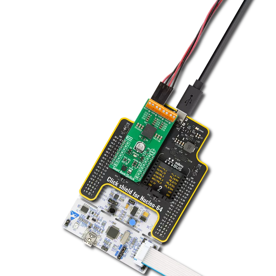
Project assembly

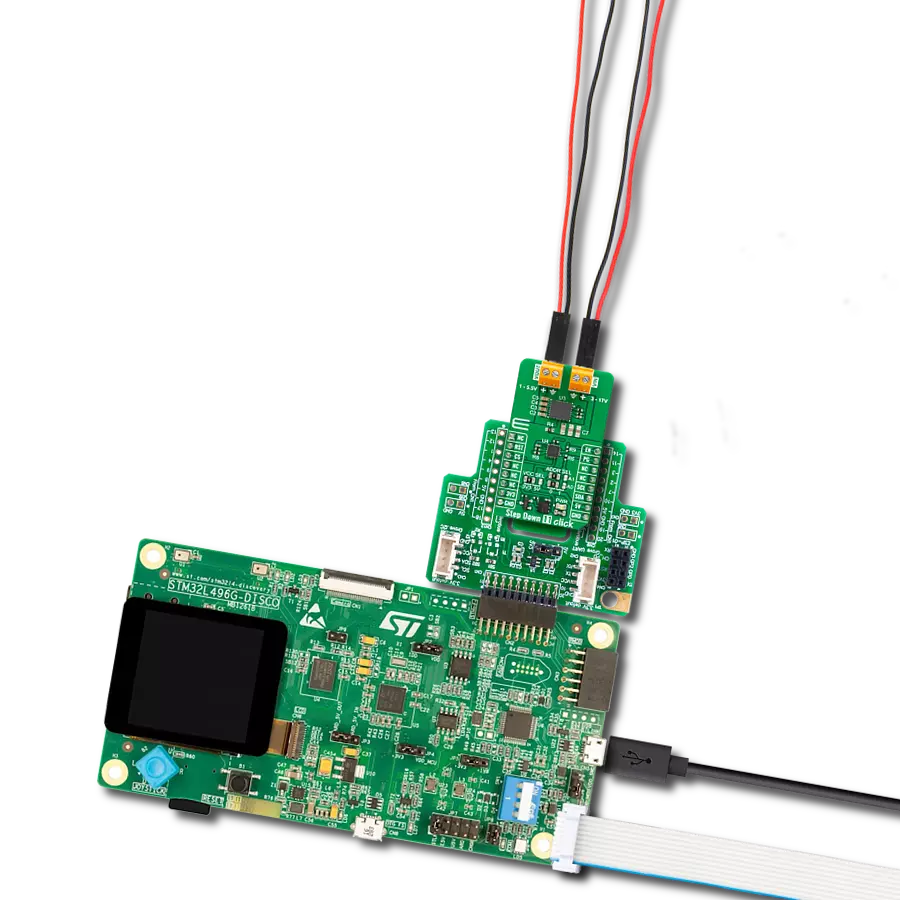
Start by selecting your development board and Click board™. Begin with the Curiosity Nano with PIC18F57Q43 as your development board.


Software Support
Library Description
This library contains API for Step Down 9 Click driver.
Key functions:
stepdown9_set_en_pin- Step Down 9 set EN pin state function.stepdown9_set_wiper_pos- Step Down 9 set wiper position.stepdown9_set_output- Step Down 9 set output voltage.
Open Source
Code example
The complete application code and a ready-to-use project are available through the NECTO Studio Package Manager for direct installation in the NECTO Studio. The application code can also be found on the MIKROE GitHub account.
/*!
 * @file main.c
 * @brief Step Down 9 Click example
 *
 * # Description
 * This library contains API for the Step Down 9 Click driver.
 * This driver provides the functions to set the output voltage treshold.
 *
 * The demo application is composed of two sections :
 *
 * ## Application Init
 * Initialization of I2C module and log UART.
 * After driver initialization, default settings sets output voltage to 1.6 V.
 *
 * ## Application Task
 * This example demonstrates the use of the Step Down 9 Click board™ by changing
 * output voltage every 5 seconds starting from 1.6 V up to 10 V.
 *
 * @author Stefan Ilic
 *
 */

#include "board.h"
#include "log.h"
#include "stepdown9.h"

static stepdown9_t stepdown9;
static log_t logger;

/**
 * @brief Output level printing function.
 * @details This function is used to log value of the selected voltage to UART terminal.
 * @param[in] sel_level : Selected voltage level.
 * @return Nothing.
 * @note None.
 */
static void print_selected_output_level ( uint8_t sel_level );

void application_init ( void )
{
    log_cfg_t log_cfg;  /**< Logger config object. */
    stepdown9_cfg_t stepdown9_cfg;  /**< Click config object. */

    /**
     * Logger initialization.
     * Default baud rate: 115200
     * Default log level: LOG_LEVEL_DEBUG
     * @note If USB_UART_RX and USB_UART_TX
     * are defined as HAL_PIN_NC, you will
     * need to define them manually for log to work.
     * See @b LOG_MAP_USB_UART macro definition for detailed explanation.
     */
    LOG_MAP_USB_UART( log_cfg );
    log_init( &logger, &log_cfg );
    log_info( &logger, " Application Init " );

    // Click initialization.
    stepdown9_cfg_setup( &stepdown9_cfg );
    STEPDOWN9_MAP_MIKROBUS( stepdown9_cfg, MIKROBUS_1 );
    if ( SPI_MASTER_ERROR == stepdown9_init( &stepdown9, &stepdown9_cfg ) )
    {
        log_error( &logger, " Communication init." );
        for ( ; ; );
    }

    if ( STEPDOWN9_ERROR == stepdown9_default_cfg ( &stepdown9 ) )
    {
        log_error( &logger, " Default configuration." );
        for ( ; ; );
    }

    log_info( &logger, " Application Task " );
}

void application_task ( void )
{
    for ( uint8_t n_cnt = STEPDOWN9_VOUT_1V6; n_cnt <= STEPDOWN9_VOUT_10V; n_cnt++ )
    {
        stepdown9_set_output( &stepdown9, n_cnt );
        log_printf( &logger, " Selected output is:" );
        print_selected_output_level ( n_cnt );
        Delay_ms ( 1000 );
        Delay_ms ( 1000 );
        Delay_ms ( 1000 );
        Delay_ms ( 1000 );
        Delay_ms ( 1000 );
    }
}

int main ( void )
{
    /* Do not remove this line or clock might not be set correctly. */
    #ifdef PREINIT_SUPPORTED
    preinit();
    #endif

    application_init( );

    for ( ; ; )
    {
        application_task( );
    }

    return 0;
}

static void print_selected_output_level ( uint8_t sel_level )
{
    switch ( sel_level )
    {
        case ( STEPDOWN9_VOUT_1V6 ):
        {
            log_printf( &logger, " 1.6V\r\n" );
            break;
        }
        case ( STEPDOWN9_VOUT_2V ):
        {
            log_printf( &logger, " 2V\r\n" );
            break;
        }
        case ( STEPDOWN9_VOUT_2V5 ):
        {
            log_printf( &logger, " 2.5V\r\n" );
            break;
        }
        case ( STEPDOWN9_VOUT_3V ):
        {
            log_printf( &logger, " 3V\r\n" );
            break;
        }
        case ( STEPDOWN9_VOUT_3V3 ):
        {
            log_printf( &logger, " 3.3V\r\n" );
            break;
        }
        case ( STEPDOWN9_VOUT_3V5 ):
        {
            log_printf( &logger, " 3.5V\r\n" );
            break;
        }
        case ( STEPDOWN9_VOUT_4V ):
        {
            log_printf( &logger, " 4V\r\n" );
            break;
        }
        case ( STEPDOWN9_VOUT_4V5 ):
        {
            log_printf( &logger, " 4.5V\r\n" );
            break;
        }
        case ( STEPDOWN9_VOUT_5V ):
        {
            log_printf( &logger, " 5V\r\n" );
            break;
        }
        case ( STEPDOWN9_VOUT_5V5 ):
        {
            log_printf( &logger, " 5.5V\r\n" );
            break;
        }
        case ( STEPDOWN9_VOUT_6V ):
        {
            log_printf( &logger, " 6V\r\n" );
            break;
        }
        case ( STEPDOWN9_VOUT_6V5 ):
        {
            log_printf( &logger, " 6.5V\r\n" );
            break;
        }
        case ( STEPDOWN9_VOUT_7V ):
        {
            log_printf( &logger, " 7V\r\n" );
            break;
        }
        case ( STEPDOWN9_VOUT_7V5 ):
        {
            log_printf( &logger, " 7.5V\r\n" );
            break;
        }
        case ( STEPDOWN9_VOUT_8V ):
        {
            log_printf( &logger, " 8V\r\n" );
            break;
        }
        case ( STEPDOWN9_VOUT_8V5 ):
        {
            log_printf( &logger, " 8.5V\r\n" );
            break;
        }
        case ( STEPDOWN9_VOUT_9V ):
        {
            log_printf( &logger, " 9V\r\n" );
            break;
        }
        case ( STEPDOWN9_VOUT_9V5 ):
        {
            log_printf( &logger, " 9.5V\r\n" );
            break;
        }
        case ( STEPDOWN9_VOUT_10V ):
        {
            log_printf( &logger, " 10V\r\n" );
            break;
        }
        default:
        {
            log_printf( &logger, " ERROR\r\n" );
        }
    }
}

// ------------------------------------------------------------------------ END
Additional Support
Resources
Category:Buck