Enjoy an impeccable performance of your bipolar stepper motors with TB9120AFTG and PIC18F57Q43
Smart. Compact. Reliable. It's all in one package!

Published Feb 13, 2024
Click board™
Stepper 11 Click
Dev. board
Curiosity Nano with PIC18F57Q43
Compiler
NECTO Studio
MCU
PIC18F57Q43
With a compact design and reliable performance, our integrated motor-driver solution takes the hassle out of managing bipolar stepper motors
A
A
Hardware Overview
How does it work?
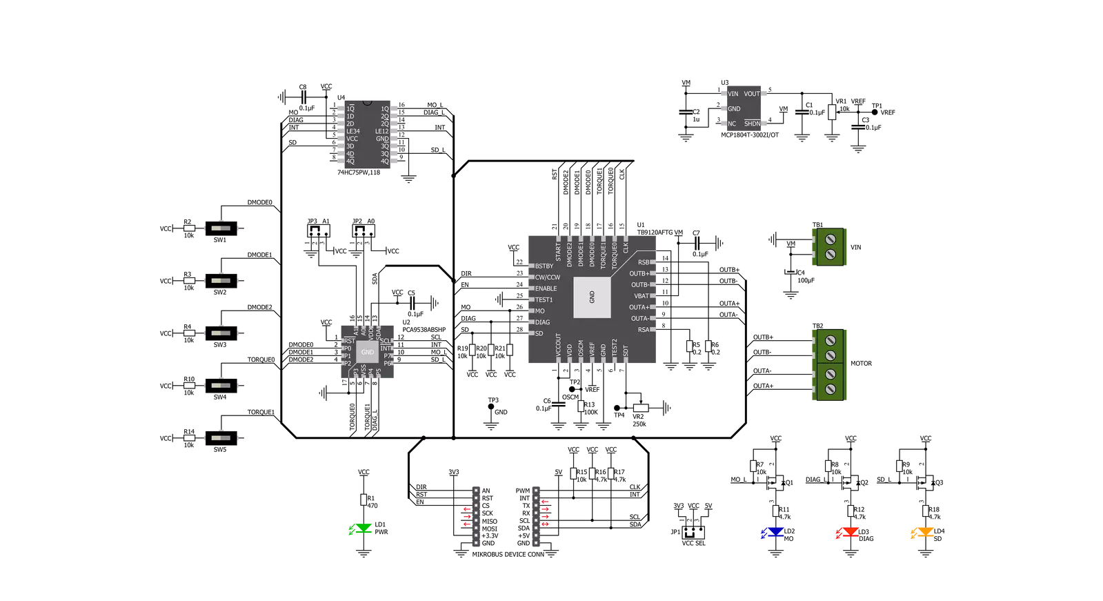
Stepper 11 Click is based on the TB9120AFTG, a constant-current 2-phase stepping motor driver for automotive applications from Toshiba Semiconductor. The TB9120AFTG incorporates low on-resistance DMOS FETs, which can deliver a 2A maximum current. A built-in mixed decay mode helps to stabilize the current waveforms. Numerous protection mechanisms are also incorporated, such as over-current and over-temperature detection, thermal shutdown, and stall detection. Thanks to the many micro-steps they support, motor noise can be significantly reduced with smoother operation and more precise control. It is suited to a wide range of general automotive applications using stepping motors and supports an operational temperature range covering -40°C to 125°C. The current value is set by the reference voltage obtained by the MCP1804, a low-dropout voltage regulator. The current threshold point for the VREF pin of the TB9120AFTG, alongside MCP1804, can be set manually using an onboard trimmer labeled VR1. Alongside I2C communication, several GPIO pins connected to the mikroBUS™ socket pins are also used to forward the information to the MCU,
associated with the PCA9538A port expander with a maximum frequency of 400kHz. The PCA9538A also allows the choice of the least significant bit (LSB) of its I2C slave address by positioning SMD jumpers labeled as ADDR SEL to an appropriate position marked as 0 and 1. The Enable pin, labeled as EN and routed to the CS pin of the mikroBUS™ socket, optimizes power consumption and is used for power ON/OFF purposes. All circuits, including the interface pins, are inactive in this state, and the TB9120AFTG is in the form of minimum power consumption. A simple DIR pin routed to the AN pin on the mikroBUS™ socket allows MCU to manage the direction of the stepper motor (clockwise or counterclockwise). At the same time, the onboard switches labeled from SW1-SW3 enable users to set the excitation mode, stepper motor step resolution, and SW4-SW5 sets torque and rotational force. In addition to these features, this Click board™ also uses the CLK step clock pin, routed to the PWM pin of the mikroBUS™ socket, for PWM constant-current control, allowing stable output waveforms in mixed decay mode. The RST pin of the mikroBUS™ socket initializes an
electrical angle in the internal counter to set an initial position. Achieving an initial position is indicated via an onboard blue LED labeled as MO. This Click board™ also has two additional LEDs for anomaly indication. Suppose a state such as a motor load open, overtemperature, or overcurrent is detected. In that case, such anomaly is indicated by a red LED marked as DIAG, while an orange LED labeled SD indicates when a stall (step-out) situation is detected. The motor-stall detection threshold can be manually set manually using an onboard trimmer labeled VR2. The Stepper 11 Click supports an external power supply for the TB9120AFTG, which can be connected to the input terminal labeled as VM and should be within the range of 7V to 18V, while the stepper motor coils can be connected to the terminals labeled as B+, B-, A-, and A+. This Click board™ can operate with either 3.3V or 5V logic voltage levels selected via the VCC SEL jumper. This way, both 3.3V and 5V capable MCUs can use the communication lines properly. Also, this Click board™ comes equipped with a library containing easy-to-use functions and an example code that can be used as a reference for further development.

Features overview
Development board
PIC18F57Q43 Curiosity Nano evaluation kit is a cutting-edge hardware platform designed to evaluate microcontrollers within the PIC18-Q43 family. Central to its design is the inclusion of the powerful PIC18F57Q43 microcontroller (MCU), offering advanced functionalities and robust performance. Key features of this evaluation kit include a yellow user LED and a responsive
mechanical user switch, providing seamless interaction and testing. The provision for a 32.768kHz crystal footprint ensures precision timing capabilities. With an onboard debugger boasting a green power and status LED, programming and debugging become intuitive and efficient. Further enhancing its utility is the Virtual serial port (CDC) and a debug GPIO channel (DGI
GPIO), offering extensive connectivity options. Powered via USB, this kit boasts an adjustable target voltage feature facilitated by the MIC5353 LDO regulator, ensuring stable operation with an output voltage ranging from 1.8V to 5.1V, with a maximum output current of 500mA, subject to ambient temperature and voltage constraints.

Microcontroller Overview
MCU Card / MCU

Architecture
PIC
MCU Memory (KB)
128
Silicon Vendor
Microchip
Pin count
48
RAM (Bytes)
8196
You complete me!
Accessories
Curiosity Nano Base for Click boards is a versatile hardware extension platform created to streamline the integration between Curiosity Nano kits and extension boards, tailored explicitly for the mikroBUS™-standardized Click boards and Xplained Pro extension boards. This innovative base board (shield) offers seamless connectivity and expansion possibilities, simplifying experimentation and development. Key features include USB power compatibility from the Curiosity Nano kit, alongside an alternative external power input option for enhanced flexibility. The onboard Li-Ion/LiPo charger and management circuit ensure smooth operation for battery-powered applications, simplifying usage and management. Moreover, the base incorporates a fixed 3.3V PSU dedicated to target and mikroBUS™ power rails, alongside a fixed 5.0V boost converter catering to 5V power rails of mikroBUS™ sockets, providing stable power delivery for various connected devices.

The 28BYJ-48 is an adaptable 5VDC stepper motor with a compact design, ideal for various applications. It features four phases, a speed variation ratio of 1/64, and a stride angle of 5.625°/64 steps, allowing precise control. The motor operates at a frequency of 100Hz and has a DC resistance of 50Ω ±7% at 25°C. It boasts an idle in-traction frequency greater than 600Hz and an idle out-traction frequency exceeding 1000Hz, ensuring reliability in different scenarios. With a self-positioning torque and in-traction torque both exceeding 34.3mN.m at 120Hz, the 28BYJ-48 offers robust performance. Its friction torque ranges from 600 to 1200 gf.cm, while the pull-in torque is 300 gf.cm. This motor makes a reliable and efficient choice for your stepper motor needs.

Used MCU Pins
mikroBUS™ mapper
Take a closer look
Click board™ Schematic
Step by step
Project assembly

Start by selecting your development board and Click board™. Begin with the Curiosity Nano with PIC18F57Q43 as your development board.


Track your results in real time
Application Output
1. Application Output - In Debug mode, the 'Application Output' window enables real-time data monitoring, offering direct insight into execution results. Ensure proper data display by configuring the environment correctly using the provided tutorial.

2. UART Terminal - Use the UART Terminal to monitor data transmission via a USB to UART converter, allowing direct communication between the Click board™ and your development system. Configure the baud rate and other serial settings according to your project's requirements to ensure proper functionality. For step-by-step setup instructions, refer to the provided tutorial.

3. Plot Output - The Plot feature offers a powerful way to visualize real-time sensor data, enabling trend analysis, debugging, and comparison of multiple data points. To set it up correctly, follow the provided tutorial, which includes a step-by-step example of using the Plot feature to display Click board™ readings. To use the Plot feature in your code, use the function: plot(*insert_graph_name*, variable_name);. This is a general format, and it is up to the user to replace 'insert_graph_name' with the actual graph name and 'variable_name' with the parameter to be displayed.

Software Support
Library Description
This library contains API for Stepper 11 Click driver.
Key functions:
stepper11_set_step_resolution- Set step resolution.stepper11_move_motor_angle- Move motor in angle value.stepper11_move_motor_step- Move motor in step value.
Open Source
Code example
The complete application code and a ready-to-use project are available through the NECTO Studio Package Manager for direct installation in the NECTO Studio. The application code can also be found on the MIKROE GitHub account.
/*!
 * @file main.c
 * @brief Stepper11 Click example
 *
 * # Description
 * This example showcases the device's ability to control the motor.
 * It initializes the device for control and moves the motor in two
 * directions in a variety of resolutions for 360 degrees.
 *
 * The demo application is composed of two sections :
 *
 * ## Application Init
 * Initialization of communication modules(I2C, UART) and additional pins
 * for control of device. Then sets default configuration that enables
 * device for motor control.
 *
 * ## Application Task
 * Firstly it rotates motor in CW direction for 360 degrees in FULL step
 * resolution. Then changes direction in CCW and rotates backwards 360 degrees
 * in 2 different step resolutions (Quarter and 1/16) in 180 degrees each.
 *
 * @author Luka Filipovic
 *
 */

#include "board.h"
#include "log.h"
#include "stepper11.h"

static stepper11_t stepper11;
static log_t logger;

void application_init ( void )
{
    log_cfg_t log_cfg;  /**< Logger config object. */
    stepper11_cfg_t stepper11_cfg;  /**< Click config object. */

    /**
     * Logger initialization.
     * Default baud rate: 115200
     * Default log level: LOG_LEVEL_DEBUG
     * @note If USB_UART_RX and USB_UART_TX
     * are defined as HAL_PIN_NC, you will
     * need to define them manually for log to work.
     * See @b LOG_MAP_USB_UART macro definition for detailed explanation.
     */
    LOG_MAP_USB_UART( log_cfg );
    log_init( &logger, &log_cfg );
    log_info( &logger, " Application Init " );

    // Click initialization.
    stepper11_cfg_setup( &stepper11_cfg );
    STEPPER11_MAP_MIKROBUS( stepper11_cfg, MIKROBUS_1 );
    err_t init_flag = stepper11_init( &stepper11, &stepper11_cfg );
    if ( I2C_MASTER_ERROR == init_flag )
    {
        log_error( &logger, " Application Init Error. " );
        log_info( &logger, " Please, run program again... " );

        for ( ; ; );
    }

    stepper11_default_cfg ( &stepper11 );

    log_info( &logger, " Application Task " );
}

void application_task ( void )
{
    stepper11_set_step_resolution( &stepper11, STEPPER11_RESOLUTION_FULL );
    stepper11_set_direction( &stepper11, 1 );
    log_info( &logger, " Rotate motor CW for 360 degrees in full step" );
    stepper11_move_motor_angle( &stepper11, 360, STEPPER11_SPEED_FAST );
    Delay_ms ( 1000 );
    stepper11_set_direction( &stepper11, 0 );
    stepper11_set_step_resolution( &stepper11, STEPPER11_RESOLUTION_QUARTER );
    log_info( &logger, " Rotate motor CCW for 180 degrees in half step" );
    stepper11_move_motor_angle( &stepper11, 180, STEPPER11_SPEED_FAST );
    Delay_ms ( 1000 );
    stepper11_set_step_resolution( &stepper11, STEPPER11_RESOLUTION_1div16 );
    log_info( &logger, " Rotate motor CCW for 180 degrees in 1/8 step" );
    stepper11_move_motor_angle( &stepper11, 180, STEPPER11_SPEED_FAST );
    Delay_ms ( 1000 );
}

int main ( void )
{
    /* Do not remove this line or clock might not be set correctly. */
    #ifdef PREINIT_SUPPORTED
    preinit();
    #endif

    application_init( );

    for ( ; ; )
    {
        application_task( );
    }

    return 0;
}

// ------------------------------------------------------------------------ END
Additional Support
Resources
Category:Stepper


