Elevate your audio experience with MCP6H012 and PIC18F47K42TQFP
The audiophile's dream: Analog active crossovers redefining sound purity

Published Feb 13, 2024
Click board™
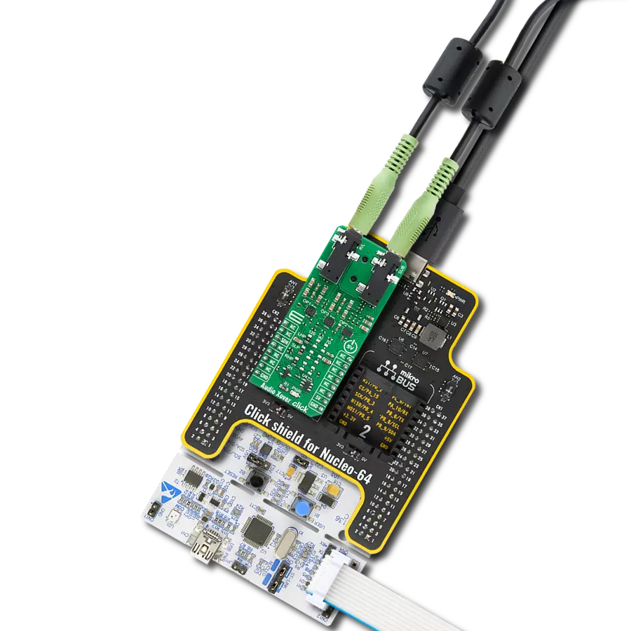
Audio Xover Click
Dev. board
Curiosity Nano with PIC18F47K42
Compiler
NECTO Studio
MCU
PIC18F47K42TQFP
Delve into the realm of high-fidelity audio with our analog active crossover solution, designed to enhance clarity and precision in two-way loudspeakers
A
A
Hardware Overview
How does it work?
Audio Xover Click is based on the MCP6H012, an operational amplifier with rail-to-rail output operation from Microchip. It uses three Butterworth filters (one for each speaker) with possibility of changing cutoff frequency between 120Hz, 90Hz and 70Hz. Butterworth filters are called maximally flat filters because, for a given order, they have the sharpest roll-off possible without inducing peaking in the Bode plot. The two-pole filter with a damping ratio of 0.707 is the second-order Butterworth filter. Audio crossovers are a type of electronic filter circuitry used in a range of audio applications, to split up an audio signal into two or more frequency ranges, so that
the signals can be sent to drivers that are designed for different frequency ranges. Active crossovers are distinguished from passive crossovers in that whereas passive crossovers split up an amplified signal coming from one power amplifier so that it can be sent to two or more drivers (e.g., a woofer and a very low frequency subwoofer, or a woofer and a tweeter), an active crossover splits up audio signal prior to amplification, so that it can be sent to two or more power amplifiers, each of which is connected to a separate driver type. Active crossovers as Audio Xover Click don’t care how powerful your amplifiers are because they process the signal
before it enters the amplifier. Active crossovers are also not very sensitive to temperature variations, so they can be very accurate, all the time. If one of the amplifiers channels in an active crossover system clips, the distortion only affects that single channel. This Click board™ can be operated only with a 5V logic voltage level. The board must perform appropriate logic voltage level conversion before using MCUs with different logic levels. Also, it comes equipped with a library containing functions and an example code that can be used as a reference for further development.

Features overview
Development board
PIC18F47K42 Curiosity Nano evaluation kit is a cutting-edge hardware platform designed to evaluate the PIC18F47K42 microcontroller (MCU). Central to its design is the inclusion of the powerful PIC18F47K42 microcontroller (MCU), offering advanced functionalities and robust performance. Key features of this evaluation kit include a yellow user LED and a responsive mechanical user switch
providing seamless interaction and testing. The provision for a 32.768kHz crystal footprint ensures precision timing capabilities. With an onboard debugger boasting a green power and status LED, programming and debugging become intuitive and efficient. Further enhancing its utility is the Virtual serial port (CDC) and a debug GPIO channel (DGI GPIO), offering extensive connectivity options.
Powered via USB, this kit boasts an adjustable target voltage feature facilitated by the MIC5353 LDO regulator, ensuring stable operation with an output voltage ranging from 2.3V to 5.1V (limited by USB input voltage), with a maximum output current of 500mA, subject to ambient temperature and voltage constraints.

Microcontroller Overview
MCU Card / MCU

Architecture
PIC
MCU Memory (KB)
128
Silicon Vendor
Microchip
Pin count
40
RAM (Bytes)
8192
You complete me!
Accessories
Curiosity Nano Base for Click boards is a versatile hardware extension platform created to streamline the integration between Curiosity Nano kits and extension boards, tailored explicitly for the mikroBUS™-standardized Click boards and Xplained Pro extension boards. This innovative base board (shield) offers seamless connectivity and expansion possibilities, simplifying experimentation and development. Key features include USB power compatibility from the Curiosity Nano kit, alongside an alternative external power input option for enhanced flexibility. The onboard Li-Ion/LiPo charger and management circuit ensure smooth operation for battery-powered applications, simplifying usage and management. Moreover, the base incorporates a fixed 3.3V PSU dedicated to target and mikroBUS™ power rails, alongside a fixed 5.0V boost converter catering to 5V power rails of mikroBUS™ sockets, providing stable power delivery for various connected devices.

Used MCU Pins
mikroBUS™ mapper
Take a closer look
Click board™ Schematic

Step by step
Project assembly
Start by selecting your development board and Click board™. Begin with the Curiosity Nano with PIC18F47K42 as your development board.


Software Support
Library Description
This library contains API for Audio Xover Click driver.
Key functions:
audioxover_power_on- Device power on function.audioxover_shut_down- Device shut down function
Open Source
Code example
The complete application code and a ready-to-use project are available through the NECTO Studio Package Manager for direct installation in the NECTO Studio. The application code can also be found on the MIKROE GitHub account.
/*!
 * \file
 * \brief Audio Xover Click example
 *
 * # Description
 * This example demonstrates the use of the Audio Xover Click board.
 * The Click is an analog active crossover solution for two-way loudspeakers.
 * The primary purpose of the crossover circuit in a loudspeaker is to split
 * an incoming audio signal into frequency bands that are passed to
 * the speaker best suited.
 *
 * The demo application is composed of two sections :
 *
 * ## Application Init
 * This function initializes the driver and makes an initial log.
 *
 * ## Application Task
 * This function enables and disables the Click board every 10 seconds,
 * and logs an appropriate message on the USB UART.
 *
 * @note
 * The hardware revision v100 of the Click board works only with MCUs that operates
 * at 5V operating voltage level.
 *
 * \author MikroE Team
 *
 */
// ------------------------------------------------------------------- INCLUDES

#include "board.h"
#include "log.h"
#include "audioxover.h"

// ------------------------------------------------------------------ VARIABLES

static audioxover_t audioxover;
static log_t logger;

// ------------------------------------------------------ APPLICATION FUNCTIONS

void application_init ( void )
{
    log_cfg_t log_cfg;
    audioxover_cfg_t cfg;

    /**
     * Logger initialization.
     * Default baud rate: 115200
     * Default log level: LOG_LEVEL_DEBUG
     * @note If USB_UART_RX and USB_UART_TX
     * are defined as HAL_PIN_NC, you will
     * need to define them manually for log to work.
     * See @b LOG_MAP_USB_UART macro definition for detailed explanation.
     */
    LOG_MAP_USB_UART( log_cfg );
    log_init( &logger, &log_cfg );
    log_info( &logger, "---- Application Init ----" );

    //  Click initialization.

    audioxover_cfg_setup( &cfg );
    AUDIOXOVER_MAP_MIKROBUS( cfg, MIKROBUS_1 );
    audioxover_init( &audioxover, &cfg );
}

void application_task ( void )
{
    log_printf( &logger, " * Switch: ON *\r\n" );
    audioxover_power_on ( &audioxover );
    // 10 seconds delay
    Delay_ms ( 1000 );
    Delay_ms ( 1000 );
    Delay_ms ( 1000 );
    Delay_ms ( 1000 );
    Delay_ms ( 1000 );
    Delay_ms ( 1000 );
    Delay_ms ( 1000 );
    Delay_ms ( 1000 );
    Delay_ms ( 1000 );
    Delay_ms ( 1000 );

    log_printf( &logger, " * Switch: OFF *\r\n" );
    audioxover_shut_down ( &audioxover );
    // 10 seconds delay
    Delay_ms ( 1000 );
    Delay_ms ( 1000 );
    Delay_ms ( 1000 );
    Delay_ms ( 1000 );
    Delay_ms ( 1000 );
    Delay_ms ( 1000 );
    Delay_ms ( 1000 );
    Delay_ms ( 1000 );
    Delay_ms ( 1000 );
    Delay_ms ( 1000 );
}

int main ( void )
{
    /* Do not remove this line or clock might not be set correctly. */
    #ifdef PREINIT_SUPPORTED
    preinit();
    #endif

    application_init( );

    for ( ; ; )
    {
        application_task( );
    }

    return 0;
}

// ------------------------------------------------------------------------ END
Additional Support
Resources
Category:Signal Processing